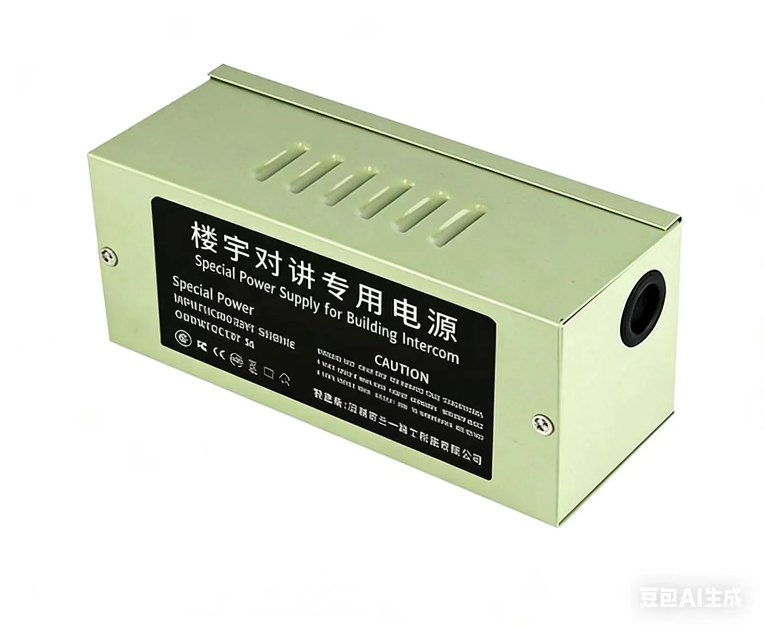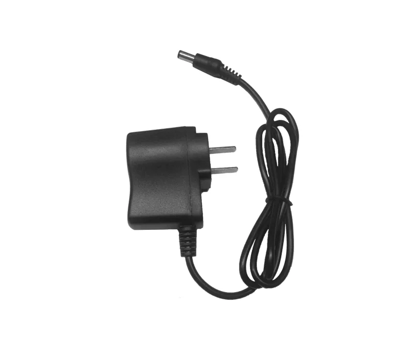
An EPS for access control, CCTV, alarm or low-voltage emergency lighting must do more than produce the correct voltage. Its behaviour must be verified during normal mains, an outage and mains restoration. The Sanyi Power® 43 Series datasheets confirm battery float charging and automatic transfer to battery when mains fails, but they do not specify one guaranteed transfer time in milliseconds. Acceptance should therefore use the real load rather than an assumed transfer-time value.
The 43 Series includes EPS-SD-4301, EPS-SP-4303, EPS-ST-4304, EPS-ST-4308 and EPS-ST-4310. Output count, current and charging capability vary by model. Before installation, a qualified installer should verify terminal order, conductor size, protective devices and the exact configuration against the selected datasheet, product label and project schematic.
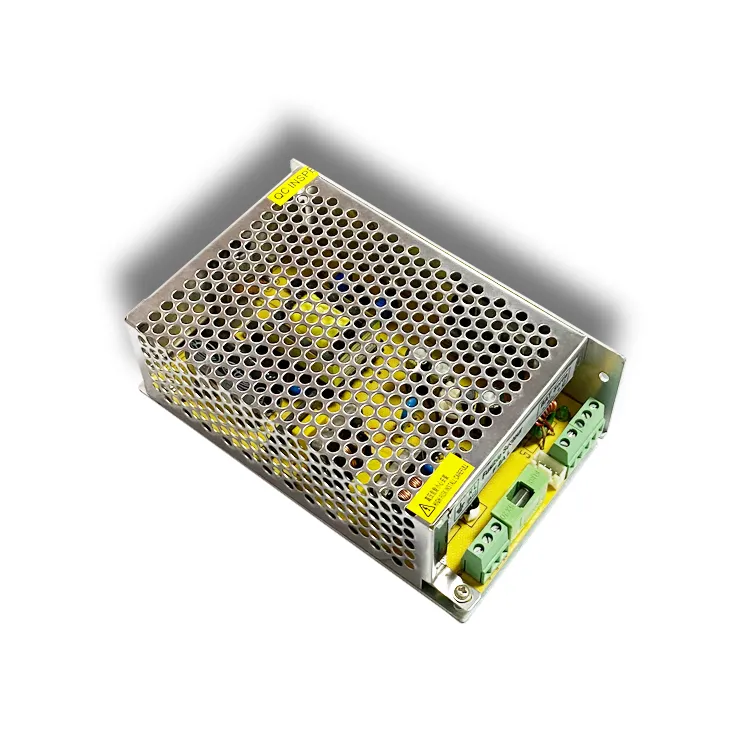
The three operating stages
| Stage | 43 Series function | What to verify on site |
|---|---|---|
| Mains available | Operates from AC 100–240V, 50/60Hz and float-charges a compatible battery | Load voltage, charging status, temperature and interference |
| Mains failure | Automatically transfers to battery supply | Whether locks, cameras, alarms or lighting restart, disconnect or misoperate |
| Mains restored | Returns to mains operation and resumes battery management | Stable load recovery and charging behaviour against the battery requirements |
Automatic transfer does not remove the need for system testing. Load hold-up, cable loss, controller undervoltage thresholds and battery condition all affect the result. The datasheets describe transfer as very short but do not provide a common number that can be used as a project guarantee.
Why a 12V system is rated at 13.5V and a 24V system at 27V
The rated outputs are:
- 12V system: DC 13.5V;
- 24V system: DC 27V.
These values support the battery float-charging function. Do not interpret “12V/24V system” as a promise of exactly 12.0V/24.0V at the bus. Before wiring, confirm the load input range, battery nominal voltage and charging requirements, and controller input range. A load that cannot accept the float-bus voltage may require a different architecture.
Output and charging-current matrix
The following values come from the exact model datasheets. Their stated test condition is 230VAC input, rated load and 25°C ambient. Total rated output current is not automatically available independently on every circuit.
| Model | 12V-family rated output | 24V-family rated output | Datasheet charging-current range |
|---|---|---|---|
| EPS-SD-4301 | 13.5V / 1.5A / 20.25W | 27V / 1A / 27W | 0–0.8A |
| EPS-SP-4303 | 13.5V / 3A / 40.5W | 27V / 1.5A / 40.5W | 0–0.8A |
| EPS-ST-4304 | 13.5V / 5A / 67.5W | 27V / 4A / 108W | 0–0.8A |
| EPS-ST-4308 | 13.5V / 10A / 135W | 27V / 5A / 135W | 0–1A |
| EPS-ST-4310 | 13.5V / 10A / 135W | 27V / 5A / 135W | 0–1A |
Download the exact PDFs from the 43 Series EPS product page. If voltage, output count or capacity has not been selected, start with the 12V/24V and 1-to-10-output selection guide.
Checks before wiring
Do not identify terminals from a product photograph. Use the model datasheet, unit label and project drawing, then complete these checks:
- isolate both mains and battery before confirming input, output, battery polarity and protective earth;
- keep the 13.5V and 27V systems, loads and batteries correctly matched;
- list steady-state and startup/actuation current for every output circuit;
- confirm battery chemistry, nominal voltage, capacity, permitted charging conditions and polarity;
- size conductors, circuit breakers or fuses for project current, cable length, temperature and local rules;
- provide thermal clearance and follow the datasheet derating across the stated -10°C to 60°C operating range;
- label every output by equipment or zone for outage testing and fault isolation.
For long low-voltage runs, use the voltage-drop calculator as an initial estimate and verify the far-end voltage with the actual load.
Float charging does not make every battery compatible
The datasheets confirm float charging, charging overvoltage/undervoltage protection and stopping charge under the stated condition to prevent overcharge. Battery compatibility still has to be engineered:
- nominal battery voltage must match the 12V or 24V system;
- chemistry-specific float voltage and allowable charge current must be confirmed;
- a 0–0.8A or 0–1A range does not by itself predict charge time for any battery;
- runtime depends on usable capacity, load, depth of discharge, ageing, temperature and cable loss;
- reverse polarity, loose terminals and aged batteries must be covered by installation and maintenance checks.
Recommended commissioning sequence
1. Pre-energisation
Verify model, voltage, terminals, polarity, earth, conductors and circuit labels. Measure battery open-circuit voltage and inspect every connection.
2. Normal-mains operation
Measure voltage at the supply and farthest load, then check all circuits, indicators and charging status. The datasheet ripple method uses a 20MHz bandwidth, a 12-inch twisted pair and 0.1μF plus 47μF capacitors at the terminal; a general multimeter reading is not equivalent to that method.
3. Outage transfer
Remove mains under controlled conditions and observe every essential load. Record controller resets, camera disconnects, relay chatter, lighting flicker and false alarms. If a transfer-time limit is contractual, measure it with appropriate test equipment rather than quoting a value absent from the datasheet.
4. Battery-backup run
Operate at the defined project load and duration while recording load voltage, battery voltage, ambient temperature and abnormal behaviour. Do not extend the test into a battery discharge condition that the battery does not permit.
5. Mains restoration
Restore mains, confirm stable load operation and verify battery management. The datasheets also list short-circuit, overload and charging overvoltage/undervoltage protection; recovery after fault removal must be checked with the exact model and load.
Frequent mistakes
- treating 13.5V/27V as a labeling error rather than the rated float-bus output;
- checking total power but not current and behaviour per output circuit;
- identifying terminals from a photograph instead of the exact datasheet and label;
- promising a fixed transfer time that the datasheet does not specify;
- ignoring voltage drop because the reading is correct only at the supply;
- treating a built-in EMI filter as proof that the complete system passes EMC.
Key specifications and project validation
All five models use AC 100–240V, 50/60Hz input. Their datasheets list 82% typical efficiency, 120mVp-p maximum ripple, a built-in EMI filter, 100% full-load burn-in, and short-circuit, overload and charging protection. The operating range is -10°C to 60°C. Project acceptance should also verify final-equipment safety and EMC requirements for the exact model, wiring, load, enclosure and destination market.
FAQ
Does the 43 Series automatically transfer to battery during an outage?
Yes, the datasheets confirm automatic transfer when mains fails. Whether the actual load remains online without a reset must still be tested.
What is the transfer time in milliseconds?
The current datasheets do not state one common millisecond value. They describe the interval as very short, so a contractual limit requires project testing.
Can every 12V device accept the 13.5V output?
Not by label alone. Check the load’s allowable input range. Equipment that cannot accept the float-bus voltage may need a different supply architecture.
What battery size can a 0–1A charger support?
The current range alone is insufficient. Confirm battery chemistry, capacity, permitted charge conditions, recovery time and ambient temperature.
May the multiple outputs be paralleled?
Do not parallel them without written confirmation. Circuit definition, protection and allowable load follow the exact model datasheet and technical agreement.
Does the EMI filter guarantee EMC compliance?
No. It is one supply feature; cables, grounding, enclosure, loads and installation determine final system behaviour.
Request a wiring and validation checklist
Send the model, 12V/24V system, load per circuit, battery type and capacity, target runtime, cable length and quantity through the Sanyi Power assistant. The engineering team will identify missing information before giving model-specific selection and validation guidance.