
If you are upgrading a solar bank, RV, marine, forklift, or e-bike pack from lead acid to LiFePO4 — or running a mixed fleet during the transition — the most expensive mistake you can make is reusing the wrong charger. The chemistries look interchangeable on a spec sheet (both are nominal 12 V, 24 V, or 48 V banks), but their charge acceptance, termination criteria, and standby behavior are fundamentally different. A charger that keeps a flooded lead acid pack alive for ten years can halve a LiFePO4 pack's life, and a charger optimized for LiFePO4 will leave a lead acid bank chronically undercharged and sulfated.
This guide compares the 3-stage / 4-stage lead acid algorithm against the CC/CV LiFePO4 profile, covers BMS handshake, and gives concrete charger picks for the major application segments — focused on LiFePO4 vs lead acid charger selection in 2026.
Why Each Chemistry Needs Its Own Charger
Lead acid is a reservoir chemistry. The plates self-discharge, accept overcharge as gassing, and benefit from a low constant float voltage that suppresses sulfation. The cell voltage curve is gently sloped — terminal voltage tracks state of charge, which is why three- and four-stage algorithms can ramp voltage up, hold absorption, and drop to float.
LiFePO4 is a flat-curve chemistry. Voltage stays near 3.2–3.3 V/cell across most of the usable capacity, then climbs sharply at the top. When current tapers below a threshold at 3.55–3.65 V/cell, the pack is full. Holding voltage longer does nothing useful, and a continuous float drives a parasitic current that ages the pack. It is not a small tuning issue — it is a different shape of curve.
Key Chemistry Differences That Drive Charger Design
| Property | Lead Acid (flooded / AGM / gel) | LiFePO4 (lithium iron phosphate) |
|---|---|---|
| Nominal cell voltage | 2.0 V | 3.2 V |
| 12 V pack composition | 6 cells | 4 cells |
| Bulk / absorption voltage (12 V) | 14.4–14.7 V | 14.2–14.6 V |
| Float voltage (12 V) | 13.2–13.8 V | None recommended |
| Equalization voltage (12 V) | 15.5–16.0 V (flooded only) | Forbidden |
| Discharge curve | Sloped, voltage tracks SoC | Flat through ~80% of SoC |
| Charge acceptance at 0 °C | Reduced ~50%, allowed | Charging forbidden below 0 °C |
| Self-discharge | 3–20% per month | <3% per month |
| Cycle life (80% DoD) | 300–800 | 3,000–6,000 |
| Has internal BMS | No (chemical management only) | Yes — gates current, opens contactors |
The single biggest design difference is that LiFePO4 packs have an electronic gatekeeper. The BMS disconnects the pack on cell overvoltage, low-temperature charge cutoff, or cell imbalance. A charger that does not respect the BMS — for example, one whose absorption voltage trips a 3.65 V/cell event — will see the pack vanish mid-cycle, misinterpret the disconnect as a fault, restart, and oscillate.
Lead acid has no such gatekeeper. Overcharge is absorbed as gassing or, in flooded cells, electrolyte loss. That is why lead acid chargers are tolerant — and why they can damage LiFePO4 packs.
Charging Algorithm Comparison: 3-Stage / 4-Stage vs CC/CV
A modern charger executes a state machine. The shape of that state machine is the difference between a healthy battery at year five and a tired one at year two.
Lead Acid: 3-Stage and 4-Stage Profiles
Bulk Stage
Maximum constant current (typically C/4 to C/10) while voltage rises toward the absorption setpoint. Bulk reaches roughly 70–80% state of charge. For a 100 Ah AGM at 20 A bulk current, expect 2.5–3 hours.
Absorption Stage
When pack voltage hits 14.4–14.7 V (12 V bank), the charger holds that voltage and lets current taper. This pushes in the last 20–30% of capacity. Absorption typically runs 1–3 hours, with current falling from the bulk value to a cutoff threshold (commonly C/50).
Float Stage
The charger drops to 13.2–13.8 V and holds it indefinitely, countering self-discharge and suppressing sulfation. A flooded battery on float can sit for months without intervention. AGM and gel use a slightly lower float to reduce gassing.
Equalization Stage (Flooded Only)
A periodic controlled overcharge at 15.5–16.0 V for 1–4 hours every 1–3 months. Equalization deliberately gasses the electrolyte to remix stratified specific gravity and reverse soft sulfation. It is prohibited on AGM, gel, and LiFePO4 — it will boil sealed cells dry or trip a BMS overvoltage shutdown.
LiFePO4: CC/CV (Two-Stage)
Constant Current (CC)
Charger pushes its rated current (commonly C/2 to 1C, far higher than lead acid will safely accept) until pack voltage reaches 14.2–14.6 V (12 V) or 3.55–3.65 V/cell. CC typically takes the pack from empty to ~90% SoC because LFP accepts current aggressively all the way up.
Constant Voltage (CV)
The charger holds 14.2–14.6 V and lets current taper. When current drops below an end-of-charge threshold (typically C/20 to C/50), charging terminates. The charger does not transition to a float stage — it stops. If voltage later drops below a re-bulk threshold, the charger restarts a full CC/CV cycle.
Two stages, hard termination — because a flat-curve chemistry with a BMS does not need anything more.
Side-by-Side Profile
| Stage | Lead Acid (12 V AGM) | LiFePO4 (12 V) |
|---|---|---|
| Bulk / CC | Constant current to 14.4–14.7 V | Constant current to 14.2–14.6 V |
| Absorption / CV | Hold 14.4–14.7 V, taper to ~C/50, 1–3 h | Hold 14.2–14.6 V, taper to C/20–C/50 |
| Float | 13.6–13.8 V indefinite | None — terminate |
| Equalization | 15.5–16.0 V (flooded only) | Forbidden |
When You Cannot Mix Chargers
Three differences make cross-use risky.
Voltage targets disagree. A lead acid bulk setpoint of 14.7 V is at or above the LiFePO4 BMS cell-overvoltage threshold once you account for cell imbalance. The BMS opens the charge contactor — the charger sees the disconnect, reads it as 0 V, and either stops or oscillates.
Termination criteria disagree. Lead acid chargers expect to transition to float. On LiFePO4, a constant 13.6 V float drives a small but persistent net charge that the BMS cannot fully reject. Over months this elevates the upper cells and shortens calendar life by years.
BMS handshake. Some LiFePO4 systems — especially server rack and golf cart packs — speak CAN or RS-485 to negotiate a charge current limit dynamically. A lead acid charger ignores the request and pushes whatever current its hardware delivers. When the BMS needs to derate, it trips the contactor instead — and the user complains that "the charger keeps cycling."
The reverse — a LiFePO4 charger on a lead acid bank — is less catastrophic but still wrong. No float means sulfation starts within days; no equalization means a flooded bank stratifies. The pack quietly loses capacity.
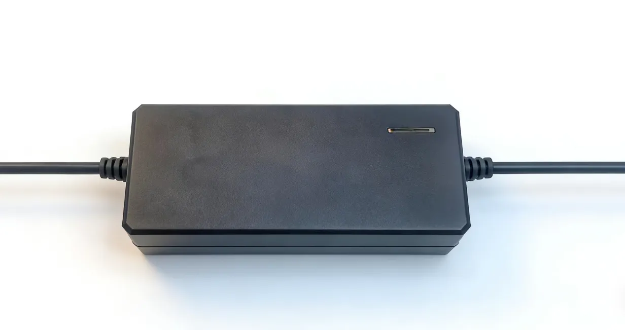
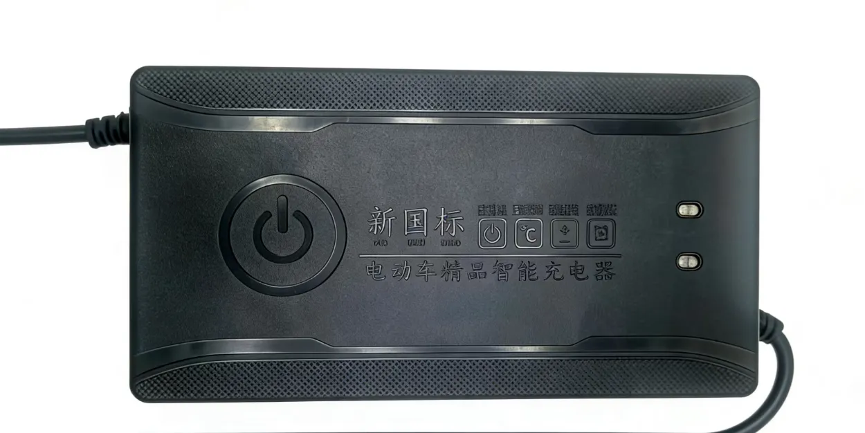
The clean answer is a multi-mode charger with selectable chemistry profiles, like the SY-C500W-10A High-Power Charger, which carries selectable lithium and lead acid modes for fleets still mid-migration.
How to Choose the Right Charger for Your Application
Solar Off-Grid
Solar systems are the cleanest argument for going LiFePO4 if you have not already. Lead acid banks are cycled 30–50% to preserve life; LFP cycles 80% daily without complaint. For a new build, pick an MPPT controller with a dedicated LFP profile and a configurable absorption/float pair (set float very low or disable it). For an existing AGM bank, a 3-stage controller with temperature compensation remains the right answer.
RV House Batteries
The RV market has largely shifted to drop-in LiFePO4 replacements. The trap is the converter/charger built into the rig — many older converters output a fixed 13.6 V "trickle" that holds an LFP pack at ~95% SoC permanently. Either replace the converter with one that has an LFP mode, or add a DC-DC charger that re-shapes the converter output into a proper CC/CV cycle. For workshop or home top-up duty between trips, a bench charger like the SY-C260W-5A High-Power Charger handles 12 V LFP packs up to ~250 Ah comfortably.
Marine
Marine wins on LFP for weight, cycle life, and freedom from venting flooded cells. The catch is temperature: many LFP BMS units block charging below 0 °C, which matters for boats stored cold. Choose a charger with low-temperature interlock awareness. IP-rated waterproofing is non-negotiable for engine-room or below-deck installation.
Forklift / Material Handling
Lead acid still has a real foothold here — flooded traction batteries with watering systems remain common in single-shift operations. For LFP-converted fleets, opportunity charging changes the math: short, high-current bursts during breaks instead of one long overnight cycle. The SY-C1000W / 1200W / 1600W Ultra High-Power Charger range is built for that high-current opportunity-charging case across both chemistries.
E-Bike and Light Electric Vehicle
E-bike pack chemistry is dictated by the OEM. For lead acid e-bikes (still common in Asia for delivery fleets), a 4-stage charger with desulfation pulse extends life by 30–50%. For LFP and Li-ion e-bikes, match the charger output voltage to the pack series count exactly — a 48 V (13S Li-ion) charger on a 48 V (15S LFP) pack will undercharge it permanently.
Industrial Backup and Standby Power
For control rooms, telecom huts, and gate/barrier systems, the charger is usually part of an Industrial Line-Frequency UPS or similar standby system. These are almost always lead acid (VRLA), with a 3-stage profile baked into the UPS firmware. LFP retrofits in this segment are growing but require a UPS that explicitly supports LFP — not all do.
FAQ
Can I use a lead acid charger on a LiFePO4 battery?
In a one-time supervised emergency, briefly — bulk current at a not-too-wrong voltage will get you home. As an ongoing setup, no: the float stage stresses the pack, equalization (if armed) trips the BMS, and calendar life drops. If you must run one charger for both, pick a multi-mode unit with a switchable LFP profile.
Why does a LiFePO4 charger not have a float stage?
Because LFP does not benefit from one. Lead acid's float counters self-discharge and suppresses sulfation; LFP's self-discharge is under 3% per month and there is no sulfation mechanism. A constant float on LFP drives a parasitic current the BMS cannot fully reject, elevating upper cells over time. The correct standby behavior is "stop, watch voltage, restart a CC/CV cycle only if voltage falls below a re-bulk threshold."
What voltage should I set for charging a 12 V / 24 V / 48 V LiFePO4 vs lead acid bank?
| Pack | Lead acid bulk/absorption | Lead acid float | LiFePO4 CC/CV target |
|---|---|---|---|
| 12 V | 14.4–14.7 V | 13.6–13.8 V | 14.2–14.6 V |
| 24 V | 28.8–29.4 V | 27.2–27.6 V | 28.4–29.2 V |
| 48 V | 57.6–58.8 V | 54.4–55.2 V | 56.8–58.4 V |
Always defer to the manufacturer datasheet — these are typical values, not absolutes.
Do I need temperature compensation on a LiFePO4 charger?
Lead acid chargers compensate by lowering absorption voltage as the battery warms (typically −3 to −5 mV/°C/cell). LiFePO4 does not need that on the high-temperature side. What it does need is a low-temperature charge cutoff — most LFP BMS units block charging below 0 °C, and a good charger respects that signal.
What about a desulfation / aging-recovery mode?
Meaningful only on lead acid. The short high-voltage pulses dislodge soft sulfate crystals from the plates. On LiFePO4 those pulses sit above the cell-overvoltage threshold and trip the BMS. Multi-mode chargers gate desulfation behind the lead acid profile — never enable it on a lithium pack.
Conclusion
LiFePO4 and lead acid look interchangeable on the bus bar and are not interchangeable at the charger. Lead acid wants a 3- or 4-stage profile with a float tail. LiFePO4 wants CC/CV, hard termination, and a charger that listens to the BMS. Mixing the two is the most common reason expensive lithium retrofits underperform.
If you are running a mixed fleet during a chemistry transition, Sanyi's high-power charger range covers selectable lithium and lead acid profiles from 260 W up to 1600 W. Get in touch with our engineering team for a sizing recommendation tailored to your pack chemistry, capacity and duty cycle.