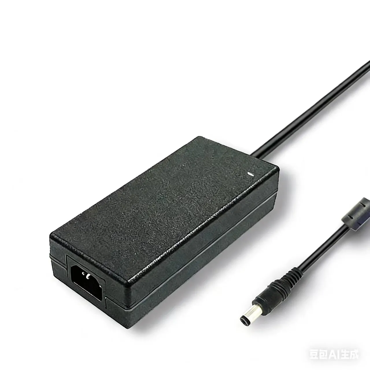

A control-cabinet integrator delivers a finished panel to a German factory floor. On the bench it powered up cleanly. On site, the moment the maintenance technician flips the upstream breaker, it trips. He resets, it trips again. Three identical 240W industrial DC supplies sit on the DIN rail, drawing perhaps 1.5A each at steady state — comfortably under the 16A C-curve breaker upstream. The math says it cannot be tripping. And yet it is.
The math is not wrong. The breaker is simply reacting to inrush current — the millisecond-long peak that occurs at AC power-on, while the bulk capacitors inside every supply charge from zero to peak line voltage. Inrush is invisible to a clamp meter and absent from most RFQ specs, but it is the single most common reason an installation that worked individually fails the moment everything is wired together.
This article is a buyer-side guide to how inrush current is created, the two dominant ways manufacturers tame it (NTC thermistor vs active limiter), and the six questions a procurement engineer should ask before signing off on a multi-PSU panel.
Why Your 16A Breaker Trips When You Power On Three 240W PSUs
The arithmetic of steady-state current makes parallel-PSU installations look trivially safe. Three 240W supplies at 230V AC pull roughly 1.0–1.2A each at full load. A 16A breaker should swallow that with margin to spare. So why do panels routinely fail commissioning the moment all three are energised together from a single upstream breaker?
The answer hides in the AC waveform during the first half-cycle after switch-on. Each switching power supply contains bulk electrolytic capacitors on its DC rail, sitting at 0V before power-up. When AC arrives, those capacitors look essentially like a short circuit until they charge — typically in 5–20 milliseconds. During that brief window, a 240W industrial supply with no inrush limiting can draw a peak current 20 to 50 times its steady-state rating. Three of them in parallel, switched on together at exactly the wrong point in the AC waveform, can demand a peak current well into the hundreds of amps for a few milliseconds.
A C-curve magnetic breaker is designed to ignore brief overloads — that is the whole point of a C curve over a B curve — but not to ignore overloads that climb past its instantaneous-trip threshold. Cross that threshold once and the magnetic element latches the breaker open. A 16A C-curve typically trips instantaneously between 5× and 10× rated, i.e. 80–160A peak. Two or three uncoordinated PSUs hitting their inrush peaks simultaneously is enough.
This is not a defective supply. It is a perfectly legitimate supply being installed in a configuration nobody specified for at procurement.
What Is Inrush Current — and Why It's 30-50× Larger Than Rated Current
The Bulk Capacitor Charging Spike
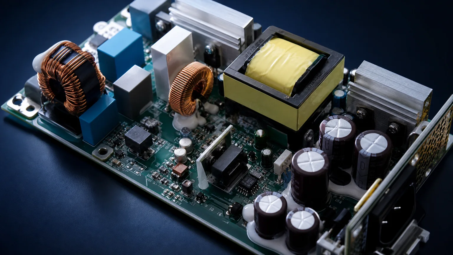
A switching power supply rectifies incoming AC into a DC rail and stores energy on a bulk electrolytic capacitor so the downstream converter sees a smooth source. That capacitor must be charged from zero to peak line voltage every time the supply is powered on. The only thing standing between the AC mains and a near-short-circuit charging current is the source impedance of the supply network plus whatever the manufacturer has chosen to put in the inrush path.
Without deliberate limiting, the inrush peak depends on line voltage at the instant of switch-on, total bulk capacitance, and the parasitic resistance of rectifier, EMI filter, and wiring. For a typical 500W industrial supply on 230V mains, the worst-case unlimited cold-start peak is in the order of 50–100A for a few milliseconds. That figure is general industry knowledge — every reputable industrial PSU datasheet publishes a comparable peak.
Cold Start vs Hot Restart
Buyers almost always overlook the second case: hot restart. After a supply has been running, the bulk capacitors are already charged. If the supply loses AC briefly (a switchgear blip, a brownout, a programmed cycle) and AC returns within a fraction of a second, the bulk capacitor is partially discharged and the inrush peak on re-energisation can be very different from a true cold start. NTC-based limiting performs beautifully on cold start and poorly on hot restart, for a thermal reason explained next.
Any specification quoting only "cold start inrush at 25°C" is telling you the easiest case. Real production environments — anywhere with grid instability or frequent maintenance switching — see hot restart constantly. A buyer who only checks the cold-start number is buying a hidden risk.
NTC Thermistor — The Cheap, Effective, but Compromised Solution
How NTC Limits Inrush
The Negative Temperature Coefficient thermistor is the most common inrush-limiting component in commodity and mid-range industrial supplies. The principle is simple: an NTC is a resistor whose resistance falls dramatically as it heats up. Cold, it might be 5 or 10 ohms. Hot, after a few seconds carrying load current, it drops below 1 ohm and dissipates an acceptably small share of total power.
At cold start, the 5–10 ohm cold resistance limits the capacitor charging current to a manageable peak — perhaps a third or a quarter of what it would otherwise be. As steady-state current flows, the NTC self-heats, its resistance collapses, and the supply runs at near-normal efficiency. Total BOM cost: pennies. No control electronics, no firmware. This is why NTC is everywhere.
The Hot-Restart Achilles Heel
The same physics that makes NTC cheap creates its dangerous weakness. After a few minutes of normal operation the NTC is hot and its resistance is low. If AC drops and returns within one or two seconds, the NTC is still hot — and therefore still low-resistance — when the bulk capacitor is partially discharged and demanding charge current again. The "limiter" is no longer limiting. The hot-restart inrush peak through a still-hot NTC can be substantially higher than the cold-start peak.
In a panel with grid instability, a poorly coordinated transfer switch, or a maintenance habit of flicking the breaker off and immediately back on, NTC-limited supplies will eventually trip an upstream breaker that they happily co-existed with for months. The maintenance technician will swear the supplies have started failing. The supplies are fine; the design just never accounted for hot restart.
This is a real procurement consideration anywhere the AC source is UPS-fed, generator-fed, or known to glitch: ask the manufacturer specifically what the hot-restart peak looks like.
Active Inrush Current Limiter — Triac/Relay Bypass
How Active Limiting Works
The premium answer to the hot-restart problem is an active limiter: a current-limiting element sits in the inrush path during the first tens of milliseconds, then a fast bypass switch (typically a relay or triac) shorts it out for normal operation. Because the bypass is logic-driven rather than thermally-driven, the limiter is fully re-armed within milliseconds of the bypass opening — a hot restart looks the same as a cold start.
A well-designed active limiter also lets the manufacturer make the inrush element bigger and slower than would be acceptable in a steady-state path, because the bypass takes over before that resistor's dissipation matters. The result is a much lower inrush peak for the same rated power, and predictable behaviour across cold start, hot restart, and brownout recovery.
When the Higher BOM Cost Pays Off
Active limiters add cost: control logic, a bypass relay or triac, a small amount of timing circuitry. Most low-end consumer adapters do not bother. Quality industrial supplies, supplies destined for parallel installation, supplies feeding latency-critical 24/7 equipment, and supplies in regulated industries (medical, railway, utility) routinely include active limiting because the alternative — random tripping under field conditions — is unacceptable.
If your application has multiple PSUs sharing one upstream breaker, frequent power cycling, generator/UPS feeds, or any history of nuisance tripping, the price premium for active limiting is recovered in the first avoided service call.
For higher-power industrial deployments — chassis above 300W where peak inrush dominates panel design — see the SW Series 500W-720W enclosed switching power supply line, which is specified for harsh-environment industrial cabinets.
Parallel PSU Installations — the Multiplier Effect
The dirtiest secret in inrush specifications is that they are quoted per supply, but breakers are sized for the panel. If three identical supplies hit their inrush peaks simultaneously, the upstream breaker sees three times one peak — assuming worst-case phase alignment, and worst-case is exactly what happens when one upstream contactor energises everything at once.
Three mitigation strategies are worth knowing, in increasing order of cost and effectiveness. The first is breaker curve selection: replacing a B-curve breaker (instantaneous 3–5× rated) with a C-curve (5–10×) or D-curve (10–20×) gives more headroom for legitimate inrush without compromising overcurrent protection. Cheapest fix, fine for moderate installations, but check local electrical code — some standards mandate a specific curve for safety reasons.
The second is phased switch-on: instead of one upstream breaker feeding all PSUs, use individual contactors with a controller that staggers energisation by 100–500ms. The aggregate inrush profile becomes a series of single-PSU peaks, none exceeding the breaker's instantaneous threshold. Adds hardware cost but is the standard approach in serious industrial cabinets.
The third is specifying actively limited supplies from the start. A supply with a low, predictable inrush peak requires neither phased switching nor an oversized breaker. The premium is paid at procurement, not in field debugging.
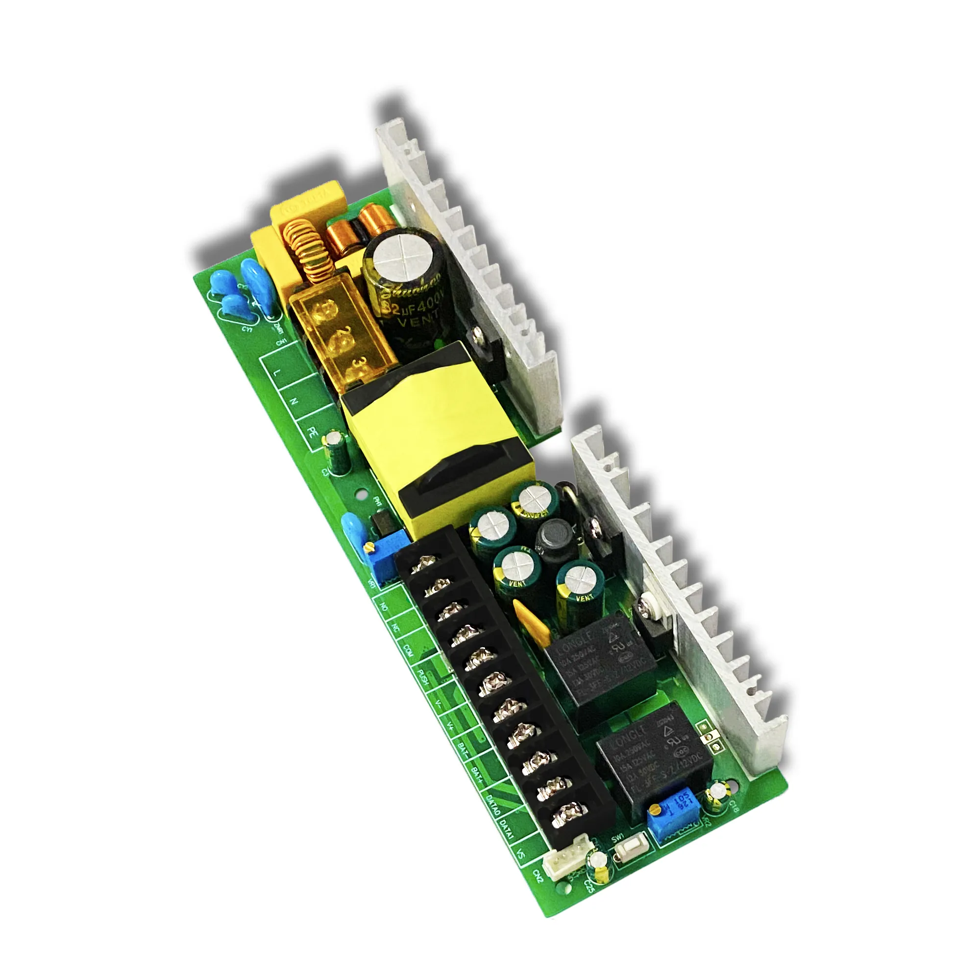
For panel-space-constrained applications with natural-convection cooling, the enclosed switching power supply family is designed for industrial cabinet integration. For board-level integration where the host equipment manages staged power-up, the SY industrial bare-board PSU options give the integrator more control.
Procurement Checklist: 6 Inrush-Related Questions Before You Sign Off
A buyer signing off on an industrial PSU specification should not accept a quote until the answer to all six of these questions is in writing. Most reputable manufacturers will provide them; lack of an answer is itself a useful signal about supplier quality.
- What is the cold-start inrush peak at nominal line voltage and at maximum line voltage? Inrush scales with line voltage; a "230V" peak number does not protect you on a 264V mains.
- What is the hot-restart inrush peak after a 1-second AC interruption? This question exposes NTC-only limiting. A supply with active limiting will quote a hot-restart peak roughly equal to its cold-start peak. NTC-only supplies will quote substantially higher, or refuse to specify.
- What is the inrush duration at half-peak? A 100A peak lasting 200 microseconds barely registers on a magnetic breaker; the same peak lasting 5ms will trip it. Duration matters as much as amplitude.
- What is the recommended upstream breaker curve and rating for N units in parallel? A manufacturer who has done the work will provide a table. A manufacturer who has not will give vague guidance, and the integrator will be the one debugging the panel on site.
- Does the limiter remain effective at the upper end of the input voltage range? Some limiter circuits are tuned around nominal voltage and degrade at the high end of a wide-input rating.
- What is the limiter's expected service life relative to the PSU's rated life? NTCs degrade with thermal cycling. Relays in active limiters have finite contact life. A supply quoting 100,000 hours MTBF that uses a relay rated for 100,000 cycles is not quite saying what its datasheet implies.
For project-specific inrush coordination and parallel-panel sizing, contact our engineering team with your breaker curves, the number of units in parallel, and the expected switching pattern; we will return a coordination assessment and the appropriate model recommendations from our catalogue, including open-frame board variants for embedded integration.
FAQ
Q1: How much inrush current does a typical 500W industrial PSU draw?
In general industry terms, a 500W industrial switching PSU on 230V AC with conventional NTC limiting draws a cold-start peak of roughly 30–50A for several milliseconds; without limiting the same supply could see 80–100A. Hot-restart peaks through a hot NTC can be considerably higher. Always check the manufacturer's specification at the input voltage and ambient temperature relevant to your installation rather than assuming a generic figure.
Q2: Why doesn't my home computer PSU trip the breaker but my industrial one does?
Modern computer PSUs (ATX-style) almost universally include active power factor correction, which incorporates an inherent soft-start of the bulk capacitor. The inrush peak is much lower and shorter than a comparably-rated commodity industrial supply with simple NTC limiting. In addition, residential 16A breakers feed exactly one device with one inrush event, whereas an industrial panel often switches several supplies on the same breaker simultaneously — the parallel multiplication is the deciding factor.
Q3: Will sequencing the power-on of multiple PSUs solve my breaker tripping?
Yes — staggered energisation by 100–500ms between units is one of the most reliable cures for parallel-PSU breaker tripping. It requires individual contactors and a sequencing controller (a small PLC or a dedicated time-delay relay chain), so it adds panel cost. For large installations the cost is trivial against the alternative; for two or three supplies, it is often cheaper to specify a higher breaker curve or actively-limited supplies and avoid the sequencing hardware entirely.
Q4: Does an active inrush limiter eliminate inrush completely?
No. An active limiter reduces the peak and makes hot-restart behaviour predictable, but the bulk capacitor still has to be charged from zero on a true cold start, and that charge requires energy from the AC mains. A well-designed active limiter typically caps the cold-start peak at something like 2–4× the supply's steady-state RMS input current and holds the hot-restart peak at a similar level. That is a dramatic improvement over uncoordinated peaks of 30–50× rated, but it is not zero — coordination with the upstream breaker is still required, just over a much wider safety margin.
.webp)