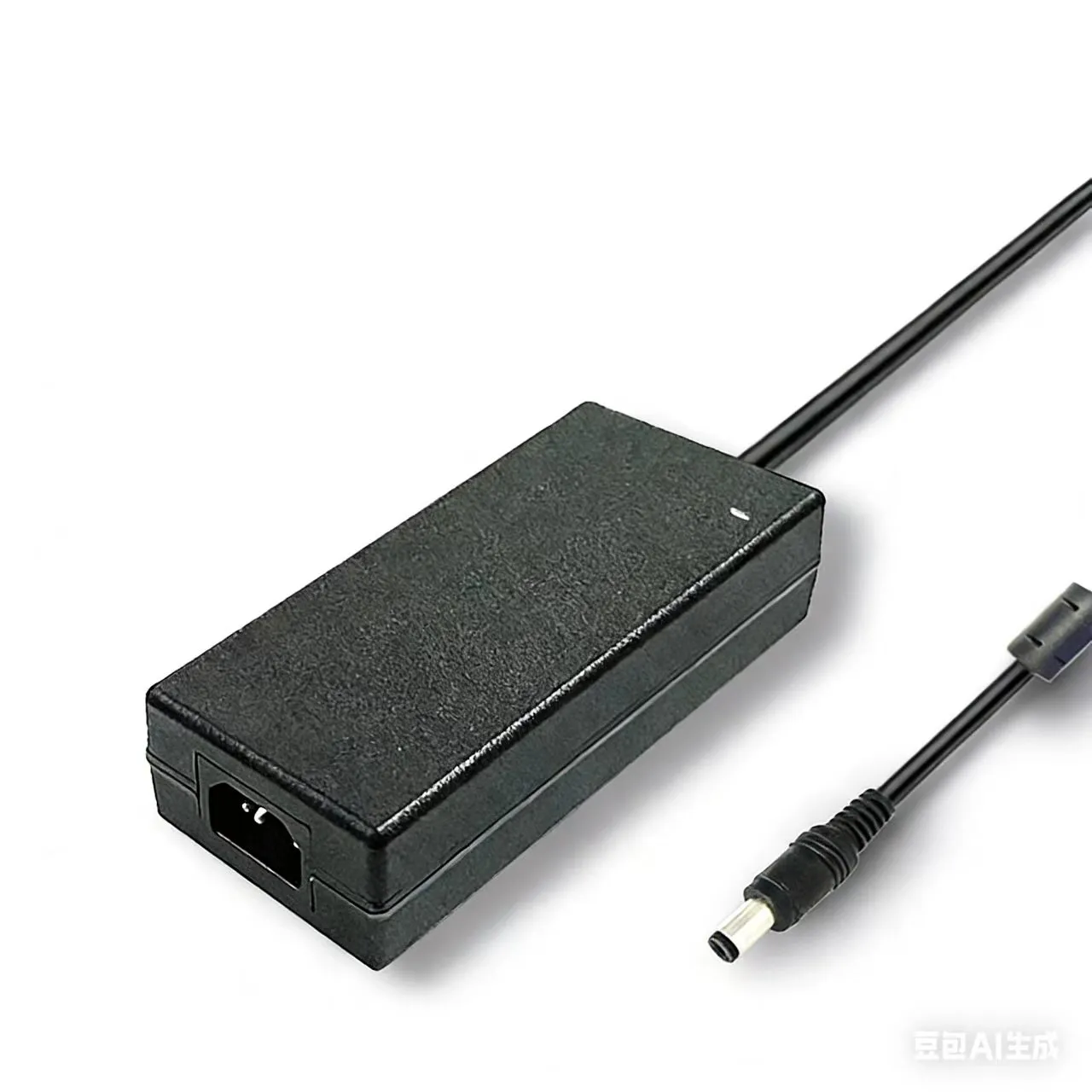

A USB-PD adapter ships with "OCP — short-circuit protected" printed in bold on its datasheet. On a customer's bench, an engineer breaks out the output rail to a header strip, brushes a probe across two adjacent pins, and shorts the rail for a fraction of a second. The protection does trip — but 50 microseconds too late. In that window the GaN primary switch sees an uncontrolled current ramp, the die exceeds its avalanche energy, and the part fails short. The field return reads "spontaneous failure." It was nothing of the sort: the spec said protected, but the response time of that protection was never the number that mattered until a real fault demanded it.
This is the gap this guide closes. "Overcurrent protection: yes" on a spec sheet is a checkbox; whether a supply survives the field is decided by which protection mode, what threshold, and how fast the loop reacts. This guide walks through the four output protections every AC-DC adapter and SMPS needs — OVP (overvoltage), OCP (overcurrent), OTP (overtemperature), and SCP (short-circuit) — plus the safety framework (IEC 62368-1 energy source classes and LPS limits) they exist to satisfy, and the abnormal-operation testing that proves they work.
The Four Output Protections at a Glance
A power supply's output protections are not interchangeable — each guards a different failure and trips on a different physical quantity. Knowing what each one watches is the starting point for specifying any of them.
| Protection | Guards against | Trips on | Typical threshold | Typical response | Recovery |
|---|---|---|---|---|---|
| OVP | Output overvoltage destroying the load | Output voltage | 110–130% of V_nom | ≤ 10 µs | Latch or auto |
| OCP | Sustained overcurrent / overload | Output / sense current | 105–150% of I_max | ms-scale (mode dependent) | CC / foldback / hiccup / latch |
| OTP | Thermal runaway, insulation aging | Internal temperature | 80–110 °C hot-spot | ms (thermal, slow) | Latch or auto with hysteresis |
| SCP | Hard output short | Sense current (fast) | Below OCP, fast comparator | ≤ 5 µs | Hiccup (shared with OCP) |
The pattern: OVP and SCP are fast, voltage/current-triggered events measured in microseconds, because the load damage they prevent happens almost instantly. OCP and OTP are slower — OCP tolerates short overloads before acting, and OTP responds to thermal mass that changes over seconds. A supply that confuses these time scales — for example a sluggish SCP — fails exactly the way the GaN adapter above did.
IEC 62368-1 Energy Source Classification: PS1, PS2, PS3
Modern AC-DC supplies are designed under IEC 62368-1, the hazard-based safety standard that replaced IEC 60950-1 and IEC 60065. Instead of classifying products by type, it classifies energy sources by how much harm they can do. For electrical power sources, the relevant axis is the Power Source (PS) class:
| Class | Power limit | Touch hazard | Design requirement |
|---|---|---|---|
| PS1 | ≤ 15 W | Not a fire/burn ignition source | May be operator-accessible |
| PS2 | ≤ 100 W | Limited — not enough to ignite under normal use | Accessible with basic safeguards |
| PS3 | > 100 W | Can ignite materials / cause injury | Must be enclosed; safeguards mandatory |
The protection circuits in this guide exist to keep a supply inside its declared class even when a fault occurs. A 90 W desktop adapter declared PS2 must not, under a single fault, dump enough energy to behave like PS3. That is precisely the job OCP, SCP, and OTP do: they bound the output energy so a fault stays in the safe envelope rather than escalating into an ignition or shock hazard. The classification defines the target; the protection circuits hit it. For the full migration picture from the legacy standards, see our IEC 62368-1 power supply safety standard migration guide.
OVP — Overvoltage Protection
OVP guards the load. If the feedback loop fails open — a cracked optocoupler, an opened feedback resistor — the converter loses regulation and drives the output toward the input rail. A 5 V rail jumping to 12 V destroys every downstream logic chip in microseconds, so OVP must be fast (≤ 10 µs) and independent of the main feedback path.
Two architectures dominate:
- Shunt-clamp OVP — a secondary-side TL431 + optocoupler branch monitors the output independently of the main regulation loop. When the output exceeds the threshold (commonly 110–130% of V_nom), it forces the controller to stop switching. This is the lower-stress, non-destructive approach.
- Crowbar OVP — an SCR across the output fires when an overvoltage comparator trips, hard-shorting the rail to ground. It is brutally fast and protects the load absolutely, but it converts an overvoltage into a dead short the OCP/SCP loop must then handle, and usually requires a fuse or a hard latch. Crowbars are reserved for cases where load survival outranks supply survival.
The recovery behavior is a deliberate choice. Latch-mode OVP stays off until the AC mains is cycled (typically off ≥ 5 s), which is the right call when the overvoltage implies a hardware fault you do not want to silently retry. Auto-recovery OVP restores output once the condition clears — appropriate when the trigger is a transient. Note one layout trap: the OVP sense node and the TL431 reference are high-impedance, so PCB parasitics and noise pickup on those traces can cause nuisance OVP trips; keep them short and guarded.
OCP — Four Modes Compared
Overcurrent protection is where most field surprises hide, because "OCP" names four genuinely different behaviors. The mode determines what the supply does while the overload persists.
| Mode | Behavior during overload | Output during fault | Recovery | Best for |
|---|---|---|---|---|
| Constant-current (CC) | Holds current at the limit, lets voltage sag | Reduced V, full I | Auto when load drops | Chargers, CC-mode loads |
| Foldback | Reduces current as voltage drops (to ≤ ~25% at short) | Low V, low I | Auto when load drops | High-power industrial, limits dissipation |
| Hiccup | Shuts off, retries after 100–200 ms, repeats | Pulsed bursts | Auto-retry | USB-PD, low average dissipation |
| Latch | Shuts off and stays off | Zero | AC cycle only | Safety-critical, no silent retry |
Constant-current simply caps the current and lets the voltage fall — clean for battery charging, but it sustains full current into the fault, dissipating heat. Foldback improves on this by reducing the current as the output voltage collapses, so a dead short draws only a fraction (≤ ~25%) of rated current, sharply limiting the heat the supply must survive — the preferred mode in high-power industrial supplies. Hiccup mode turns the converter off entirely on detecting overcurrent, waits 100–200 ms, then attempts a restart; under a persistent fault it delivers short bursts at a low duty cycle (5–10%), keeping average dissipation tiny — which is why USB-PD adapters favour it. Latch simply shuts down until AC is removed, used where a silent automatic retry is itself a hazard. High-power industrial designs commonly combine foldback for the overload region with hiccup for hard faults; compact USB-PD designs lean on hiccup alone.
SCP — Short-Circuit Protection
SCP is OCP's fast sibling. A hard short is the most violent fault a supply sees: current rises at the rate the output inductance allows, and without a fast cutoff the primary switch's current rating is exceeded before a slow OCP loop reacts — exactly the GaN failure from the opening story. SCP therefore runs through a dedicated fast comparator on the current-sense path with a response target of ≤ 5 µs, well ahead of the normal OCP threshold.
The heart of both OCP and SCP is current sensing, and the sense element is a real trade-off:
- Sense-resistor (R_sense) — a low-value resistor (0.01–0.05 Ω) in the current path; the voltage across it feeds the comparator. Simple and accurate, but it burns power: at 10 A, a 0.05 Ω resistor dissipates 5 W — choosing 0.1 Ω here to "be safe" would waste 10 W, which is why R_sense value is a balance of accuracy against loss, not a maximize-for-margin decision.
- Low-side sensing references the resistor to ground (simple, but the load no longer shares a clean ground), while high-side sensing measures in the positive rail (cleaner system ground, needs a high-side amplifier or sense-FET).
- Sense-FET uses the switch's own R_DS(on) or a mirror FET as the sense element, eliminating the discrete resistor's loss at the cost of accuracy that drifts with temperature.
Under a sustained short, the loop runs in hiccup at a 5–10% duty cycle: brief restart attempts separated by long off-times, so the average power into the short stays low and the supply does not cook itself waiting for the fault to clear. SCP and OCP share this current-sense front end — they are two thresholds on one circuit, not two circuits.
OTP — Overtemperature Protection
OTP is the slow guardian. Thermal faults — a blocked vent, a failed fan, a derating violation, a high ambient — build over seconds to minutes, and left unchecked they age insulation, dry out electrolytics, and ultimately run away. Because the danger is thermal, the trigger is temperature and the response is comparatively slow; speed is not the issue, placement is.
Two implementations:
- NTC + comparator + optocoupler — an NTC thermistor at the hot spot feeds a comparator with a fixed threshold (e.g., trip at 85 °C, release at 80 °C for a 5 °C hysteresis so the supply does not chatter on and off at the threshold). Simple, cheap, robust.
- MCU + ADC multi-point — a microcontroller reads several NTCs (transformer, primary switch, output MOSFET) and applies thresholds per node, enabling smart derating before a hard trip and richer diagnostics.
Like OVP, OTP can be latch-mode (stay off until manually reset — safest against repeated thermal stress) or auto-recovery with hysteresis (restart once cool, suited to outdoor units that cycle through temperature naturally). The single most common OTP mistake is sensor placement: an NTC mounted in the cooling airflow rather than on the heat source lags the real junction temperature by a minute or more, so the supply trips long after the damage is done. OTP also ties directly to the derating curve — pulling output back as temperature rises extends life and keeps the hard trip a last resort.
UL 60950-1 / IEC 62368-1 Limited Power Source (LPS)
Beyond the PS classes, a supply may need to qualify as a Limited Power Source (LPS) — an output so bounded that, even under fault, it cannot ignite a fire or deliver a dangerous shock, which lets downstream wiring and enclosures use relaxed construction. The classic limits combine current and apparent power:
- Output ≤ 8 A and ≤ 100 VA under any condition (one common combination; other rows pair, e.g., ≤ 5 A with ≤ 100 VA).
- Crucially, the limits must hold under abnormal operation, not just normally — which is exactly what the protection circuits enforce.
- LPS overlaps but is not identical to NEC Class 2 (≤ 60 V and ≤ 100 VA) — Class 2 is a wiring/installation category, LPS is a power-source property; a design often targets both.
So an LPS-rated output is a promise the protection circuits keep: OCP and SCP must cap current and VA inside the limit even when something fails, or the LPS claim evaporates.
Abnormal Operation Test — Proving the Protection Works
A protection circuit that works on the bench under a clean short is not yet qualified. Safety standards require abnormal operation testing, where the supply is subjected to realistic faults and must still not catch fire, deliver a shock, or exceed its declared PS class. The core cases:
- Single-fault (component short / open) — short or open one component at a time (a feedback resistor, an optocoupler, a switch) and confirm the supply stays safe.
- Output short-circuit — hard-short the output and confirm SCP holds, with no fire and no thermal escape.
- Output overload — load beyond rating and confirm OCP keeps the output bounded.
The pass criterion is not "the supply survives" — it is that no single failure produces an unsafe outcome. That is why protections are layered: OVP catches loop failure, OCP/SCP catch load faults, OTP catches thermal faults, and together they ensure no one fault crosses into PS3-level hazard. This abnormal-operation discipline is the run-time counterpart to the start-up safety checks covered in our Hi-Pot, insulation resistance and touch current safety verification guide — Hi-Pot proves the insulation at power-on, abnormal-operation testing proves the protection during a fault.
Reverse-Polarity Protection and Redundancy
Two adjacent topics round out output-side protection. Reverse-polarity protection guards against a miswired or reverse-connected output:
- A P-channel MOSFET in the high side passes current with near-zero drop in normal polarity and blocks reverse current, with a V_GS clamp (Zener) to protect the gate — the low-loss modern choice.
- A series Schottky diode is simpler but drops ~0.3–0.5 V continuously, wasting power at high current — acceptable only on low-current rails.
For availability, N+1 redundancy parallels supplies through OR-ing FETs (active ideal-diode controllers) instead of OR-ing Schottky diodes, eliminating the ~0.7 V diode drop and its heat while still isolating a failed unit. One layout note across all of this: the output Y-capacitor used for common-mode noise and the crowbar/clamp paths share the output node, so their leakage and clamp voltages must be reconciled — a Y-cap leakage path can interact with a sensitive OVP sense node if grounding is careless.
Five Protection-Circuit Debug Pitfalls
Most protection failures are not exotic — they are predictable design and layout mistakes that surface only when a real fault arrives:
- Optocoupler aging drifts the OVP threshold. An optocoupler's current-transfer ratio (CTR) degrades over years; an OVP set by an aging opto can drift its trip point +20% and fail to fire when needed. Budget margin for end-of-life CTR, or sense OVP independently of the regulation opto.
- Oversizing R_sense. Picking 0.1 Ω "for margin" on a 10 A rail dissipates ~10 W — an unacceptable efficiency and thermal penalty. Size R_sense to the comparator's real threshold voltage, not to the largest resistor that fits.
- Hiccup period too short. A retry interval that is too fast (or a sense filter that is too aggressive) makes the converter restart into the fault repeatedly, producing an audible/EMI oscillation and stressing the switch. Set the hiccup off-time long enough that average dissipation stays low.
- Undeclared latch reset time. A latch-mode design that needs AC off for 5–10 s to reset will generate "won't restart" complaints if that requirement is never documented — state the reset condition in the manual.
- NTC in the airflow, not on the heat source. An OTP sensor in the cooling path lags the real hot-spot by a minute or more, so the trip fires long after thermal damage. Mount the NTC on the actual heat source — transformer core or switch heatsink.
Sanyi Power Supply Ecosystem — Four-Layer Protection, Verified
Sanyi designs its USB-PD, desktop and industrial power lines with all four protections — OVP + OCP + OTP + SCP — engineered together rather than bolted on, and verified under IEC 62368-1 abnormal-operation testing so the output stays inside its declared PS2 envelope even under single fault. The HP high-power adapter series (up to 240W) pairs fast SCP with foldback-plus-hiccup OCP for high-current rails, while the APN desktop adapter series applies the same protection discipline across mid-power desktop and IT loads. For dense multi-port charging, the SY-C260W multi-mode charger and the higher-output SY-C500W high-power charger balance fast GaN switching against microsecond-class SCP so a shorted port never reaches the primary switch.
Because protection is a system property — threshold, mode, response time and thermal placement all at once — our supplies are characterized to the abnormal-operation cases your destination standard actually requires. Contact our power engineering team with your rail voltages, fault tolerances, recovery preference (latch vs auto) and target safety class, and we will recommend a platform whose protection envelope matches.
FAQ
Is latch-mode or auto-recovery protection safer? It depends on what the fault implies. Latch-mode is safer when the fault means hardware damage — a feedback failure causing OVP, or a thermal runaway — because silently retrying into a damaged supply can escalate the hazard; it forces a human to power-cycle and (ideally) investigate. Auto-recovery is preferable for transient faults — a momentary overload or a brief over-temperature on an unattended outdoor unit — where staying latched off would be a needless outage. Many designs mix them: auto-recovery OCP for overloads, latch for OVP and hard OTP.
Does hiccup mode affect EMI? It can, if it is mis-tuned. The repeated on/off bursting of hiccup creates low-frequency energy and, if the retry period is too short, an audible or EMI oscillation as the converter restarts into the fault. A correctly designed hiccup uses a long enough off-time (low duty cycle, ~5–10%) that the bursts are infrequent and the average dissipation — and the EMI signature — stays low. The fix for hiccup EMI complaints is almost always lengthening the retry interval, not abandoning the mode.
Where should the OTP NTC be mounted for an accurate trip? On the actual heat source, not in the cooling airflow. The hottest, most failure-prone nodes are the transformer core, the primary switch, and the output rectifier/MOSFET — mount the NTC in thermal contact with one of those (or use multi-point MCU sensing to cover several). An NTC placed in the air stream reads the moving air, not the junction, and lags the real temperature by a minute or more, so it trips long after the damage is done.
Are LPS and PS2 the same thing? No. PS2 is an IEC 62368-1 energy-source class (≤ 100 W) that governs how accessible an output may be and what safeguards it needs. LPS (Limited Power Source) is a separate construction property — an output bounded in current and VA (e.g., ≤ 8 A, ≤ 100 VA) even under fault — that lets downstream wiring use relaxed rules. They overlap in intent (both bound output energy) but are evaluated by different criteria, and a design can be PS2 without meeting LPS, or target both. NEC Class 2 is yet another, wiring-focused category.
How do I choose R_sense so it's both accurate and efficient? Work backward from the comparator. Pick the sense voltage the OCP/SCP comparator needs at the trip current (often tens of millivolts), then size R_sense to produce exactly that — no larger. A bigger resistor gives more signal but burns power as I²R, so the right value is the smallest one that still gives the comparator a clean, noise-immune threshold. If that resistor's loss is still unacceptable at high current, move to high-side sensing with an amplifier or a sense-FET, which recover the signal without the dissipation of a large series resistor.
.webp)