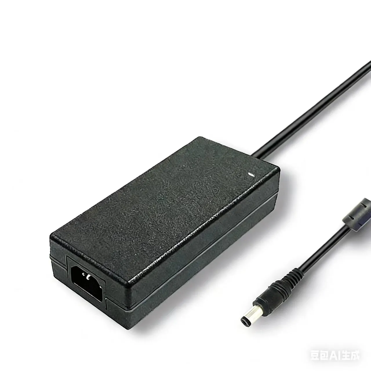

A datasheet says "MTBF 100,000 hours." A buyer reads that as "11.4 years," specs the supply into a 24/7 industrial gateway, and three years later a batch of units starts dropping out of the field. The customer is furious — "you promised 100,000 hours!" — and the support engineer has to explain, awkwardly, that the number never meant what everyone assumed. Nobody lied. The MTBF figure was real. It was simply calculated to a different standard, at a different temperature, and it never described how long a single unit would live.
This guide untangles the four reliability-prediction frameworks behind that 100,000-hour number — IEC 61709, Telcordia SR-332, MIL-HDBK-217F and FIDES — and explains why the same AC-DC power supply can earn wildly different MTBF figures depending on which one you use. It is the fourth pillar of power-supply compliance: after safety, EMC and efficiency comes reliability prediction — the math of how long the design actually runs.
Reliability Terms Clarified: MTBF / MTTF / MTTR / Availability / FIT
Most MTBF arguments are really vocabulary arguments. Five terms do all the work:
| Term | Meaning | Applies to |
|---|---|---|
| MTBF | Mean Time Between Failures — average uptime between repairs | Repairable systems |
| MTTF | Mean Time To Failure — average life until first failure | Non-repairable units |
| MTTR | Mean Time To Repair — average downtime per repair | Service planning |
| FIT | Failures In Time — failures per 10⁹ device-hours | Component reliability |
| Availability | Uptime fraction = MTBF / (MTBF + MTTR) | System SLAs |
The single most important point: MTBF is not the lifetime of one unit. An MTBF of 100,000 hours means that across a large population running in the flat part of their life, the aggregate failure rate is one failure per 100,000 cumulative operating hours. Run 1,000 units for 100 hours each and you have 100,000 unit-hours — so on average you'd expect about one failure in that batch. It says nothing about whether your individual unit lasts 3 years or 15. FIT and MTBF are reciprocals: MTBF (hours) = 10⁹ / FIT.
IEC 61709 — The European Industrial Default
IEC 61709 (current edition 2017) is the European reference for component reliability data and the stress models used to adjust it. It does not hand you a finished MTBF; it standardises the reference conditions and the π (pi) factors that translate a component's base failure rate to your real operating point.
The reference conditions anchor everything: a reference temperature of Tref = 40 °C, nominal voltage, and defined stress ratios. Real-world deviations are corrected with multiplicative factors — π_T for temperature (via Arrhenius), π_U for voltage stress, π_I for current stress, and so on. IEC 61709 is especially explicit about electrolytic capacitors, treating their wear-out as a first-class lifetime model rather than a flat failure rate, which is why it tends to produce realistic, sometimes sobering, numbers for designs that run hot.
Telcordia SR-332 — The Telecom Standard (ex-Bellcore)
Telcordia SR-332 (Issue 4, 2016) descends from the old Bellcore TR-332 and is the dominant standard for telecom and datacom equipment, where carriers demand five-nines (99.999%) availability. Its defining feature is that it blends three data sources:
- Method I — parts-count using Telcordia's generic failure rates.
- Method II — Method I adjusted with laboratory test data (burn-in and life-test results).
- Method III — Method II further adjusted with field-return data from units actually deployed.
Because Telcordia can fold in lab and field evidence, and because its generic rates were calibrated for benign indoor telecom environments, it usually yields more optimistic (higher) MTBF numbers than the military standard for the same circuit. That optimism is appropriate for a climate-controlled central office — and misleading if your supply lives on a pole or in a sealed outdoor cabinet.
MIL-HDBK-217F — The Military Standard Still in Use
MIL-HDBK-217F Notice 2 (1995) is officially withdrawn, yet it remains a de-facto reference because so many aerospace and defense contracts still cite it. It offers two methods: Parts Count (early design) and Parts Stress Analysis (detailed, component-by-component). Its hallmark is the environment factor π_E, which spans an enormous range — from "ground, benign" (a lab) to "airborne, uninhabited, cargo" or "missile, launch." Apply a harsh π_E and the predicted failure rate climbs steeply.
MIL-HDBK-217F is widely regarded as conservative (pessimistic): its 1990s-era component data predates modern semiconductor and capacitor quality, so it often forecasts shorter life than reality. That conservatism is a feature for safety-critical defense gear and a handicap for commercial benchmarking — which is exactly why the same supply scores so differently across standards.
FIDES Guide and Siemens SN 29500 — Two More You'll Meet
Two further frameworks round out the landscape. FIDES Guide 2009 was developed by a French aeronautics-and-defense consortium; it explicitly models lifecycle stresses (thermal cycling, vibration, humidity) and process/quality factors for the manufacturer and supply chain, making it more physics-of-failure oriented than the older parts-count methods. Siemens SN 29500 is a corporate standard widely used in European industrial automation, providing a coherent set of base failure rates and conversion models aligned with IEC 61709. You won't usually pick these unless a customer's contract names them — but when a spec says "predict per FIDES," it is asking for the lifecycle-aware approach, not a generic parts count.
Parts Count vs Parts Stress — Two Prediction Methods
Every standard offers a fast method and a thorough one, and the gap between them is large:
- Parts Count — assumes each component runs at a default stress level; you simply tally components by type and quality and sum their generic rates. Fast, used early in design when the BOM exists but the operating points don't. Tends to be pessimistic because it assumes worst-typical stress everywhere.
- Parts Stress — uses each component's actual voltage, current and temperature stress ratios. Far more labor-intensive (you need the real schematic and thermal data) but much more accurate, and usually more optimistic because a well-derated design runs most parts well below their limits.
For the same power supply, Parts Count and Parts Stress predictions commonly differ by 2–5×. Use Count for early go/no-go, Stress for the number you put on a datasheet.
Electrolytic Capacitor Lifetime and the Arrhenius Rule
In most AC-DC supplies, the reliability bottleneck is the electrolytic capacitor. Its electrolyte slowly evaporates, ESR rises, ripple-handling falls, and the supply eventually fails — a true wear-out mechanism, unlike the random failures MTBF describes. Its life follows the Arrhenius "10-degree rule": every 10 °C reduction in capacitor core temperature roughly doubles life (and every 10 °C rise halves it).
Starting from a 105 °C, 5,000-hour rated capacitor, the rule projects life at lower operating temperatures:
| Capacitor core temp | Life multiplier vs 105 °C | Projected life |
|---|---|---|
| 105 °C (rated) | 1× | 5,000 h (~0.6 yr) |
| 85 °C | 4× | 20,000 h (~2.3 yr) |
| 65 °C | 16× | 80,000 h (~9.1 yr) |
| 45 °C | 64× | 320,000 h (~36 yr) |
This is why specifying 105 °C long-life electrolytics and keeping the capacitor cool through derating matters far more to real-world endurance than chasing a bigger MTBF number. The judgment criterion is typically an ESR increase to 2× initial value, or capacitance dropping below 80% of rated.
The Bathtub Curve — Where MTBF Actually Applies
Failure rate over a product's life traces a bathtub curve with three regions:
- Infant mortality — early failures from manufacturing defects; the rate falls steeply. Removed by burn-in.
- Useful life — a low, roughly constant random failure rate. This flat region is the only place MTBF is valid.
- Wear-out — the rate climbs as components (especially electrolytics) degrade. MTBF does not describe this region.
The crucial insight: a constant-failure-rate MTBF model assumes you have burned off infant mortality and have not yet entered wear-out. Quote MTBF for a unit that's into its capacitor wear-out phase and the number is meaningless.
Four-Standard MTBF Comparison — Same Supply, Different Numbers
Here is the heart of the confusion. Take one hypothetical 240 W AC-DC industrial adapter and predict its MTBF four ways, holding the design constant and varying only the standard and its assumptions:
| Standard | Method / basis | Typical environment assumed | Indicative MTBF | Relative |
|---|---|---|---|---|
| MIL-HDBK-217F | Parts Stress, 1990s data | Ground benign → harsh | ~150,000 h | 1.0× (most pessimistic) |
| IEC 61709 | Stress + electrolytic model | Tref 40 °C industrial | ~350,000 h | ~2.3× |
| FIDES 2009 | Physics-of-failure lifecycle | Controlled industrial | ~550,000 h | ~3.7× |
| Telcordia SR-332 | Method I, benign telecom | Central office, 25–40 °C | ~900,000 h | ~6.0× |
Same hardware, a 6× spread. None of these numbers is "wrong" — they answer different questions under different assumptions. The lesson for any datasheet or RFQ: an MTBF figure without its standard, method and temperature is not a specification. Always ask "per which standard, at what temperature?"
Five Common MTBF Misuse Pitfalls
- Reading MTBF as single-unit lifetime. "100,000 hours" is a population failure rate, not a guarantee your unit survives 11 years. The electrolytic wear-out limit, not MTBF, sets real service life.
- Quoting MTBF without temperature. A number at 25 °C and the same design at 55 °C differ by several times. No stated temperature = no usable number.
- Skipping burn-in. Without burn-in you ship in the infant-mortality region, where the real failure rate is far above the MTBF model's flat assumption.
- Ignoring capacitor aging. A great MTBF means nothing if the electrolytics enter wear-out at year 3. Reliability prediction and lifetime modeling are two different calculations — you need both.
- Mis-computing N+1 redundancy. Adding a redundant supply raises system availability but doesn't multiply a single unit's MTBF; the math must account for repair time (MTTR) and common-cause failures, or the redundancy benefit is overstated.
Sanyi Power Supply Ecosystem — Engineered for Predictable Life
Reliability is designed in, not calculated after the fact. Sanyi specifies 105 °C long-life electrolytic capacitors and applies conservative component stress derating so that — per the Arrhenius table above — the capacitor wear-out limit sits comfortably beyond the target service life, not just the MTBF number. For high-power industrial and AV use, the HP adapter series (120W–480W) is built around derated thermal margins; the APN desktop adapter series (48W–144W) targets long-duty office and networking loads. For high-current charging duty, the SY-C260W smart charger and SY-C500W workstation charger carry the same long-life capacitor and derating philosophy so the reliability prediction and the real field life actually agree.
Reliability is the fourth pillar alongside safety, EMC and efficiency. For the safety axis see our IEC 62368-1 safety standard migration guide; for the thermal derating that drives the Arrhenius life above, see the derating curve guide for temperature and altitude; and for the EMC emissions axis, the CISPR 32 vs FCC Part 15 Class B EMI guide.
Need an AC-DC adapter, charger or industrial supply with a documented MTBF prediction (IEC 61709, Telcordia SR-332 or MIL-HDBK-217F) at your operating temperature? Contact our power engineering team with your power, ambient and target-life requirements and we'll recommend a solution with the matching reliability data.
FAQ
Does MTBF mean my power supply will last that many hours? No. MTBF is a population statistic — the average operating hours between failures across many units in their useful-life region. A 100,000-hour MTBF doesn't mean one unit runs 100,000 hours; real single-unit service life is usually limited by electrolytic capacitor wear-out, which you calculate separately with the Arrhenius model, not MTBF.
Which standard gives the strictest MTBF — and which the most generous? MIL-HDBK-217F is the most pessimistic (1990s component data, harsh environment factors). Telcordia SR-332 is usually the most optimistic for benign telecom conditions. IEC 61709 and FIDES sit in between. The same supply can show a 6× spread, so always compare like-for-like: same standard, method and temperature.
Is the electrolytic capacitor really the lifetime bottleneck? In most AC-DC supplies, yes. Electrolytics dry out and lose capacitance via a temperature-driven wear-out mechanism that MTBF doesn't capture. Specifying 105 °C long-life parts and keeping them cool through derating extends real service life far more than chasing a bigger MTBF figure.
How do I calculate MTBF for an N+1 redundant system? You can't just multiply one unit's MTBF. Redundancy raises availability, but the system reliability formula must include repair time (MTTR) and common-cause failures. A 1-out-of-2 (N+1) configuration improves availability dramatically only if failed units are repaired quickly; ignore MTTR and you'll overstate the benefit.
Can burn-in extend a power supply's life? Burn-in doesn't extend life — it removes infant-mortality failures so shipped units start in the flat useful-life region where the MTBF model is valid. It improves delivered reliability and makes the MTBF number meaningful, but it does not push back the eventual capacitor wear-out limit.
.webp)