A European distributor once returned an entire pallet of switching power supplies that had passed safety, passed efficiency, and passed high-frequency EMI — yet were still illegal to sell. The reason was invisible on a bench: each unit pumped distorted, non-sinusoidal current back onto the grid, overshooting the EN 61000-3-2 harmonic limits. In one three-phase installation the same defect quietly overloaded the shared neutral conductor until it overheated, because every supply injected the same third-harmonic current and those currents added up in the neutral instead of cancelling. That is the failure mode this guide exists to prevent.
EN 61000-3-2 (harmonic current emission) and EN 61000-3-3 (voltage fluctuation and flicker) are the two low-frequency EMC gates that decide whether a power supply is allowed onto the European mains at all. They sit below 2 kHz — a completely different band from the high-frequency EMI covered by CISPR 32 — and they are the quiet reason that almost any adapter above 75 W now needs Active Power Factor Correction.
Why a PFC-Deficient Supply Gets Bulk-Rejected in the EU
Harmonic current is not a cosmetic spec. Under the EU EMC Directive (2014/30/EU), EN 61000-3-2 and EN 61000-3-3 are harmonised standards that underpin the CE mark for any mains-connected electronic product up to 16 A per phase. A supply that exceeds the harmonic limits is non-compliant the moment it is placed on the market — regardless of how clean its conducted and radiated emissions are.
The physics is unforgiving. A classic SMPS front end is a bridge rectifier feeding a bulk capacitor: it draws current only in narrow spikes near the AC voltage peak, producing a current waveform rich in odd harmonics (3rd, 5th, 7th…). Each of those harmonics is current the grid never asked for. The third harmonic is the worst actor: in a three-phase, four-wire system the third-harmonic currents from all three phases are in phase and sum in the neutral rather than cancelling, so a room full of cheap supplies can drive neutral current above phase current and cook the wiring. Treating EN 61000-3-2 as a day-one design constraint — not a final-week surprise — is what separates a shippable platform from a returned pallet.
The Low-Frequency EMC Standard Set at a Glance
Three documents define the low-frequency emission picture for mains equipment:
- EN / IEC 61000-3-2 — harmonic current emissions for equipment with input current ≤ 16 A per phase. This is the one almost every adapter and SMPS must meet.
- EN / IEC 61000-3-3 — voltage changes, voltage fluctuations and flicker for equipment ≤ 16 A per phase connected without conditional connection.
- EN / IEC 61000-3-11 and 61000-3-12 — the higher-power siblings for equipment drawing 16 A to 75 A per phase (flicker and harmonics respectively), often under conditional connection rules.
EN 61000-3-2 asks "how much distorted current do you inject?" EN 61000-3-3 asks "how much do you make the grid voltage wobble?" Together they cover the emission side below 2 kHz. They are the low-frequency mirror of the high-frequency emission story told in our CISPR 32 vs FCC Part 15 Class B EMI compliance guide — same goal (control what you put back on the mains), different band.
EN 61000-3-2 Explained: Harmonics 2 Through 40
EN 61000-3-2 limits each individual harmonic of the input current from the 2nd up to the 40th order — i.e. up to roughly 2 kHz on a 50 Hz grid. The currently harmonised edition is EN IEC 61000-3-2:2019 (with A1:2021), mirroring the IEC text so a single design target serves both the EU standard and its international parent.
The pivotal number for adapter engineers is the 75 W threshold. For Class D equipment, products with active input power at or below 75 W are effectively exempt from the harmonic limits (a power-level relaxation applies in the 75–600 W band, and below 75 W no limit applies). Above 75 W the mA-per-watt limits bite hard, and meeting them with a passive front end becomes impractical — which is precisely why Active PFC becomes near-mandatory past that line. Note the exemption is class-specific: it is not a blanket "anything under 75 W is free" rule, a misreading that ends careers in returned-goods meetings.
Equipment Classes A, B, C and D
EN 61000-3-2 sorts every product into one of four classes, and the class determines which limit table applies. Getting the class wrong invalidates the whole compliance file.
| Class | Scope | Typical examples | Limit basis |
|---|---|---|---|
| Class A | Balanced three-phase equipment, and everything not covered by B/C/D (the default bucket) | Tools (non-portable), most appliances, generic SMPS | Fixed absolute limits in amperes |
| Class B | Portable tools, and arc-welding equipment that is non-professional | Hand drills, portable power tools | Class A limits × 1.5 |
| Class C | Lighting equipment | LED drivers, luminaires | THD-based % limits; split at the 25 W line |
| Class D | Equipment with a "special" pulse-shaped input current, ≤ 600 W | PCs, monitors, TVs, many adapters/SMPS | mA-per-watt limits |
Two traps dominate. First, Class D is power-capped at 600 W — above 600 W the equipment moves to Class A limits, not the mA/W table. Second, Class C lighting splits at 25 W: above 25 W the full power-factor and harmonic limits apply, while at or below 25 W a lighter alternative set is allowed. An adapter feeding general electronics is almost always Class D; mislabelling it Class A is one of the most common compliance errors.
EN 61000-3-3 Explained: Voltage Fluctuation and Flicker
EN 61000-3-3 governs how much an appliance makes the supply voltage move as its load changes — the effect you see as lights flickering when a heavy load switches. It defines several limits that must all be satisfied:
- d(max) — maximum relative voltage change, limited to ≤ 4 %.
- d(c) — relative steady-state voltage change, limited to ≤ 3.3 %.
- d(t) — the period during which the relative voltage change exceeds 3.3 % must be ≤ 500 ms per change event.
- P(st) — short-term flicker severity (10-minute window), limited to ≤ 1.0.
- P(lt) — long-term flicker severity (2-hour window, aggregated from twelve P(st) values), limited to ≤ 0.65.
P(st) and P(lt) are not measured with an ordinary meter — they come from a flickermeter defined by IEC 61000-4-15, which models the lamp-eye-brain response so that the number reflects perceived annoyance, not raw voltage. For a steady-load adapter this is usually easy; it gets interesting for supplies with large, repetitive inrush or load-step behaviour.
EN 61000-3-11 and EN 61000-3-12: Above 16 A
Once input current passes 16 A per phase, the ≤16 A standards no longer apply and two higher-power documents take over:
- EN 61000-3-11 — the flicker standard for equipment 16 A to 75 A per phase, typically under conditional connection (the installer must verify the supply network impedance is low enough).
- EN 61000-3-12 — the harmonic-current standard for the same 16–75 A range, expressed largely through the short-circuit ratio R(sce) of the connection point.
Most adapters never reach this tier, but large industrial supplies and parallel-rack installations do — and engineers who only know the ≤16 A standards can be blindsided when a high-current system is assessed under 3-11/3-12 instead.
Harmonic Limit Values: The Numbers That Matter
Two limit philosophies coexist. Class A uses fixed absolute current limits (in amperes) per harmonic order; Class D uses limits normalised to power (mA per watt) plus an absolute ceiling. The table below shows representative key orders.
| Harmonic order | Class A limit (A, absolute) | Class D limit (mA/W) |
|---|---|---|
| 2nd (even) | 1.08 | — |
| 3rd (odd) | 2.30 | 3.4 |
| 5th (odd) | 1.14 | 1.9 |
| 7th (odd) | 0.77 | 1.0 |
| 9th (odd) | 0.40 | 0.5 |
| 11th (odd) | 0.33 | 0.35 |
| 13th (odd) | 0.21 | 0.296 |
For Class C lighting above 25 W the limits are expressed as a percentage of the fundamental (e.g. 3rd harmonic ≤ 30 % × power factor, 5th ≤ 10 %, 7th ≤ 7 %), with a required power factor that effectively forces a corrected front end. The practical message across all classes: the 3rd and 5th harmonics are where uncorrected supplies fail first, and they are exactly what PFC suppresses.
Low-Frequency vs High-Frequency EMC: EN 61000-3-2/3 vs CISPR 32
A power supply has to clear both low-frequency emission (harmonics/flicker) and high-frequency emission (EMI). They are completely separate test regimes that engineers routinely confuse.
| Aspect | EN 61000-3-2 / 3-3 | CISPR 32 / EN 55032 |
|---|---|---|
| Frequency band | < 2 kHz (DC–40th harmonic) | 9 kHz – 1 GHz (and above) |
| What it controls | Distorted current drawn from the mains + voltage flicker | Electromagnetic field / noise emitted |
| Limit units | Amperes, mA/W, % THD, P(st)/P(lt) | dBµV (conducted), dBµV/m (radiated) |
| Test equipment | Harmonics analyser, flickermeter (IEC 61000-4-15), reference impedance | LISN, EMI receiver, antenna, anechoic chamber |
| Compliance role | "How much harmonic current you push back" | "How much electromagnetic field you radiate" |
| Fixed by | Power Factor Correction (Active PFC) | EMI filter (X/Y caps, common-mode choke), shielding |
The two regimes are emission siblings; the immunity counterpart — how a supply survives surges and ESD instead of emitting — is covered in our IEC 61000-4 surge, ESD and EFT immunity test guide.
PFC and EN 61000-3-2: A Near-Mandatory Relationship
Above 75 W, Active PFC is effectively the only practical route to EN 61000-3-2 compliance. An active PFC stage forces the input current to track the voltage sinusoid, collapsing the harmonic content and driving power factor toward unity. The compliance equivalence engineers rely on: a corrected front end achieving THD < 10 % and power factor > 0.9 will comfortably sit inside the Class D limit table.
Passive PFC — an inductor plus filtering — can nudge a borderline Class D design under the limits at low power, but it is bulky, load-dependent, and runs out of margin quickly as power rises. The full trade-off between the two topologies, and how PFC ties into 80 PLUS efficiency, is the subject of our Active vs Passive PFC selection guide. The key distinction: that guide explains how to meet the limit (the solution); this guide explains what the limit is (the standard).
When Voltage Flicker Actually Bites
Flicker problems are rarer than harmonic problems for steady adapters, but they appear in predictable situations: large inrush current at switch-on, abrupt load steps in high-power converters, weak rural or end-of-line grids with high source impedance, and — most insidiously — the aggregate effect of many residential SMPS switching together. A single adapter may pass P(st) easily, yet a population of identical supplies on a weak feeder can collectively degrade local voltage quality, which is why EN 61000-3-3 uses a reference network impedance to standardise the test condition. Designing soft-start inrush limiting in from the beginning is the cheapest insurance against a late flicker failure.
Five Common Low-Frequency EMC Pitfalls
- Assuming everything under 75 W is exempt. The 75 W relaxation is Class D specific. A misclassified product, or a Class A/C device, does not get the free pass.
- Filing a Class D product as Class A. PCs, monitors, TVs and many adapters are Class D with mA/W limits — and Class D is capped at 600 W, above which it reverts to Class A. Both directions are easy to get wrong.
- Active PFC designed badly, breaking d(max). A PFC stage with poorly controlled startup or load transients can pass harmonics yet overshoot the 4 % d(max) voltage-change limit of EN 61000-3-3. Harmonics and flicker are separate tests; passing one does not guarantee the other.
- Ignoring third-harmonic accumulation in the neutral. In three-phase, four-wire installs, third-harmonic currents add in the neutral instead of cancelling. A fleet of nominally-compliant supplies can still overload shared neutral wiring.
- Class C lighting misjudged at the 25 W split. LED drivers above 25 W face the full power-factor and harmonic regime; below 25 W a lighter set applies. Misreading which side of the line you are on invalidates the lighting compliance file. A close cousin: PFC that switches off at light load, letting harmonics spike during low-power standby operation that the test then catches.
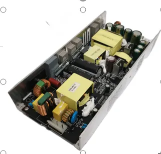
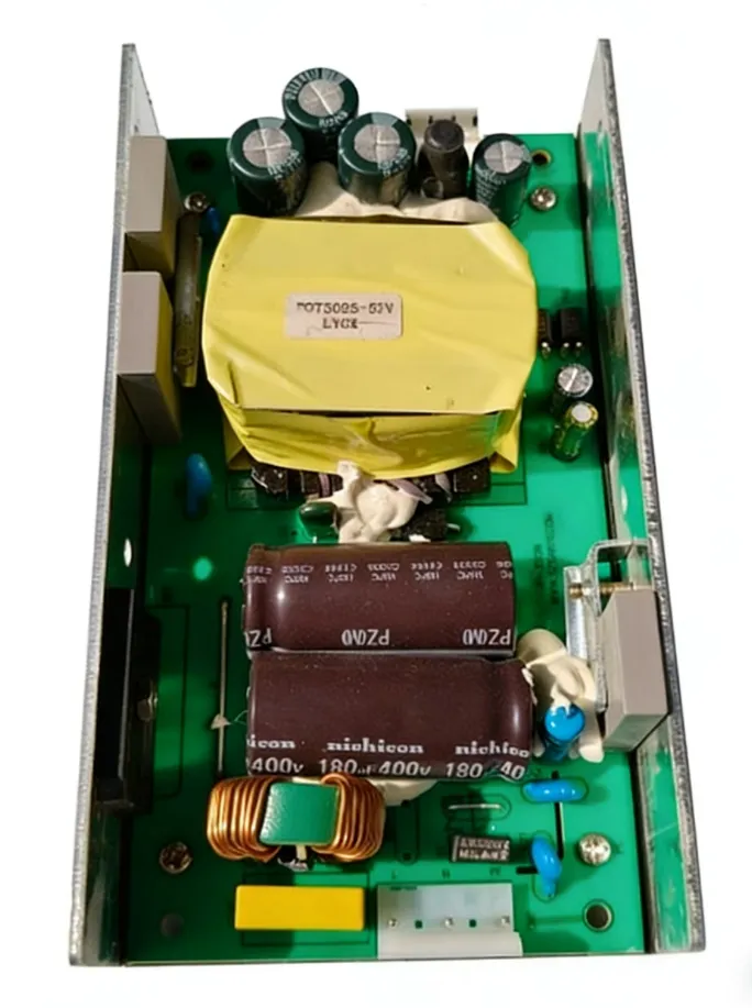
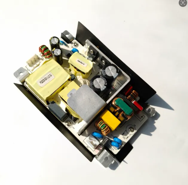
Sanyi Power Supply Ecosystem — Active PFC Across the Line
Sanyi designs its USB-PD, desktop and industrial adapter platforms with Active PFC wherever the power level demands it, so products clear EN 61000-3-2 Class D harmonic limits and EN 61000-3-3 flicker limits together with the high-frequency EMI work in the same chassis. For high-power applications, the HP high-power adapter series (up to 240W) carries the active PFC front end needed to hold the mA/W limits well above the 75 W threshold. The APN desktop adapter series brings the same low-frequency discipline to mid-power desktop and IT loads. For dense, high-output charging, the SY-C260W multi-mode charger and the higher-output SY-C500W high-power charger are engineered with corrected front ends so harmonic current and voltage flicker stay inside limits at full load.
Because low-frequency EMC, high-frequency EMI, safety and efficiency are one interlocking compliance set, our adapters are built to satisfy all of them at once. Contact our power engineering team with your power level, class and destination-market requirements and we will recommend a compliant platform with matching test data.
FAQ
Is any power supply under 75 W completely exempt from EN 61000-3-2? Not universally. The 75 W exemption is Class D specific — for equipment with the special pulse-shaped input current. A Class A or Class C product, or a misclassified one, does not automatically get the pass. Always confirm the equipment class first, then check whether the power-level relaxation actually applies.
How do I tell whether my adapter is Class A or Class D? Class D covers PCs, monitors, TVs and equipment with a "special" pulse-shaped input current waveform, rated ≤ 600 W — which is most consumer adapters and SMPS. Class A is the default bucket for balanced three-phase equipment and anything not matching B/C/D, and it also catches Class D devices that exceed 600 W. The waveform shape and the 600 W cap are the deciding factors.
How are P(st) and P(lt) flicker values actually measured? With a flickermeter defined by IEC 61000-4-15, not an ordinary voltmeter. It models the lamp-eye-brain response to voltage fluctuation. P(st) is the short-term severity over a 10-minute window (limit ≤ 1.0); P(lt) aggregates twelve P(st) values over two hours (limit ≤ 0.65). The device is tested against a standardised reference network impedance.
Is Active PFC the only way to pass EN 61000-3-2? Below 75 W (Class D) you may not need it at all. Between roughly 75 W and a few hundred watts, passive PFC can sometimes squeak under the limits but is bulky and load-dependent. Above that, Active PFC is effectively mandatory — it is the reliable route to THD < 10 % and power factor > 0.9, which sits comfortably inside the Class D limit table.
How does EN 61000-3-2 relate to CISPR 32? They are complementary halves of emission compliance. EN 61000-3-2/3-3 control low-frequency behaviour below 2 kHz — distorted current and voltage flicker, fixed by PFC. CISPR 32 controls high-frequency emissions from 9 kHz to 1 GHz — conducted and radiated noise, fixed by the EMI filter and shielding. A supply must pass both; clearing one says nothing about the other.