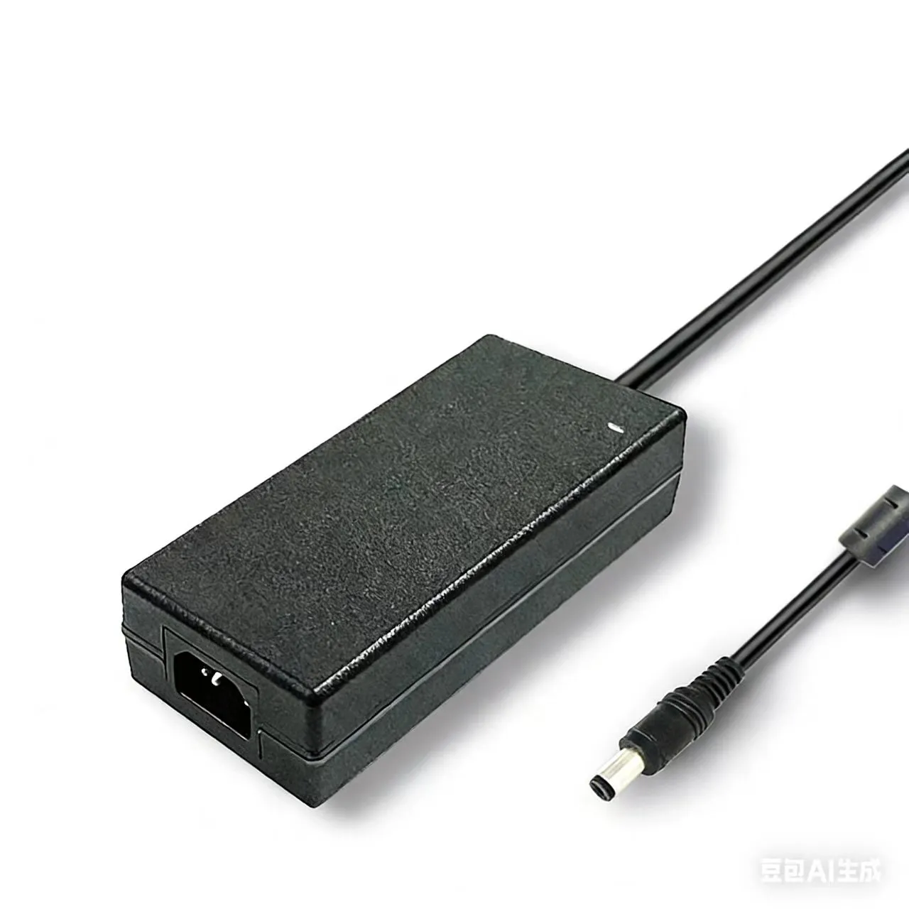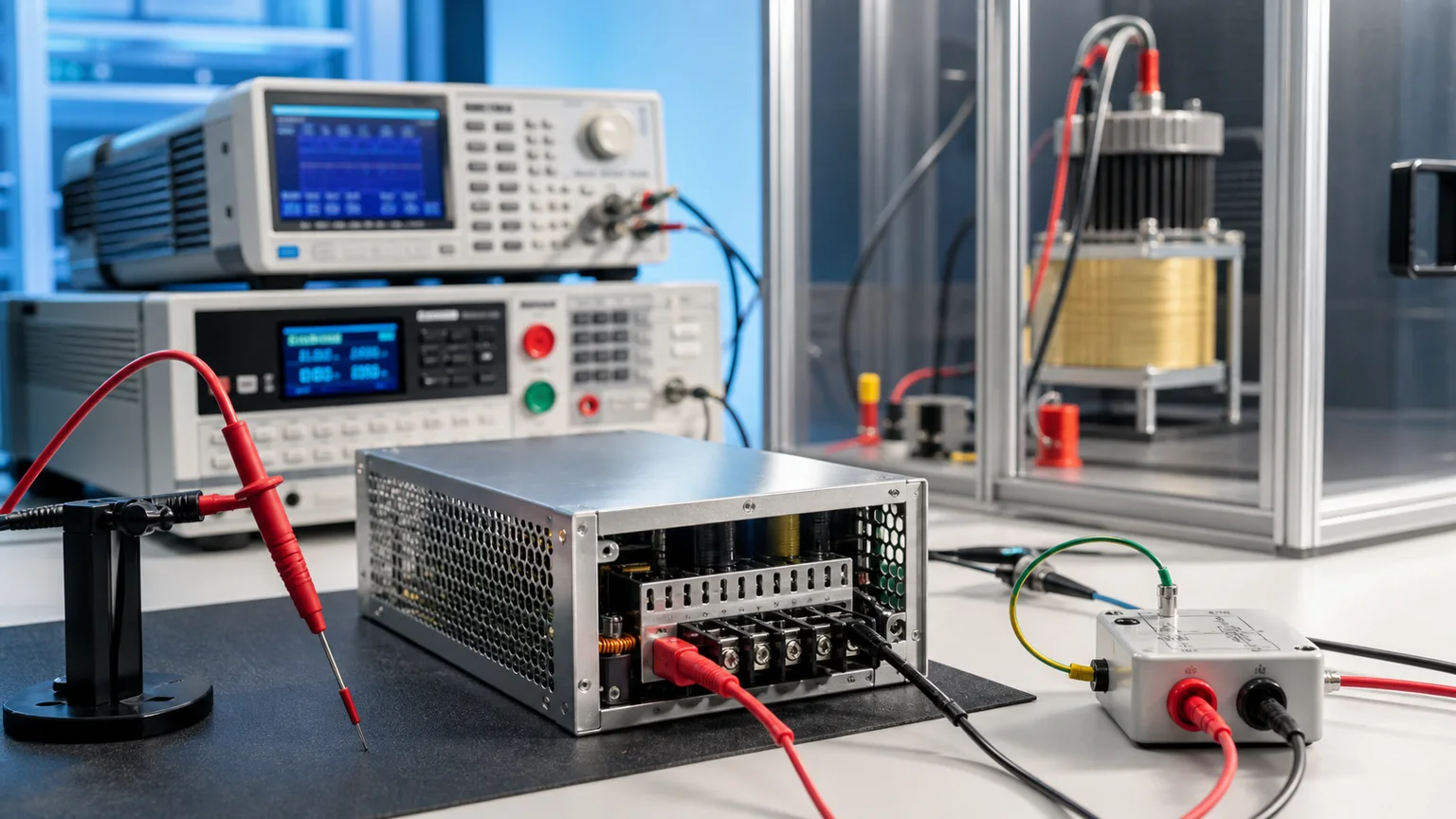

A power supply can carry a flawless safety certificate and still ship a unit that kills someone. The certificate — a CB report or a national listing — is granted on a handful of golden samples that passed a type test. It says the design is safe. It says nothing about the transformer on line 4, shift 2, whose margin-thin edge insulation slipped through. One real field story makes the gap concrete: a converter that cleared its full type-test file came back with a 0.3% breakdown rate in volume — a sub-visible varnish void at a transformer winding edge, invisible to the CB sample, lethal in production. The design was safe; the units were not.
That gap is closed by safety verification testing — the electrical proof, applied to hardware rather than to a report, that the isolation barrier between mains and the user is intact. This guide compares the three pillars of that proof — Hi-Pot dielectric withstand, insulation resistance (IR), and touch/leakage current — for external adapters and SMPS: what each one proves, the IEC 62368-1 energy-source framework behind them, the AC 3000 VAC vs DC 4242 VDC numbers, the medical IEC 60601-1 step-up, why a 60 s type test cannot run on a production line, and five debug pitfalls that turn a good design into a Hi-Pot reject pile.
Why "IEC 62368-1 Certified" ≠ Every Unit Is Safe
Certification and production are tested by completely different regimes, and conflating them is the costliest mistake in power-supply safety. A type test (a.k.a. design qualification) is run once, on a few representative samples, at full severity — 60 s of Hi-Pot, full IR characterisation, touch-current measurement across operating conditions. It proves the design and the materials chosen are safe. But a transformer with a pinhole in its tape, a creepage gap shrunk by a misplaced component, a Y-cap soldered to the wrong pad — none of these are design faults. They are production defects, and the only thing that catches them is a routine test: a fast, 100% in-line electrical check on every single unit. Skip it, and the 0.3% that the golden samples never represented walk out the door. The safety listing is necessary; it is not sufficient. This guide is the production-floor twin of our IEC 62368-1 power supply safety standard migration guide — that one explains how the standard classifies hazards; this one explains how you verify every unit against them.
The Three Pillars of Safety Verification
For an external power supply, electrical safety verification rests on three complementary measurements, each defending against a different failure of the mains-to-user barrier:
- Hi-Pot (dielectric withstand): apply a high voltage far above normal across the isolation barrier and confirm it does not break down. It proves the insulation can survive a transient overvoltage without arcing — the catastrophic, shock-and-fire failure.
- Insulation Resistance (IR): apply a moderate DC voltage and measure the resistance of the barrier. It proves the insulation is not degraded, damp or contaminated — the slow, ageing failure that Hi-Pot can miss.
- Touch / Leakage Current: measure the current that would flow through a person touching the output or enclosure during normal operation. It proves that even an intact barrier does not leak enough current to be felt or to be dangerous.
The three are not interchangeable. Hi-Pot is a pass/fail stress test; IR is a quality measurement; touch current is a normal-condition safety limit. A unit must pass all three.
IEC 62368-1 Energy Source Classification: ES1 / ES2 / ES3
Modern safety design starts not with "is it insulated" but with "how much energy is behind the barrier." IEC 62368-1 (the hazard-based standard that replaced IEC 60950-1 and IEC 60065) classifies every electrical energy source by its capacity to cause an electric-shock injury, and that class dictates how much isolation is required:
| Energy source | Voltage limit (approx.) | Shock risk | Isolation requirement |
|---|---|---|---|
| ES1 | ≤30 Vrms / ≤60 VDC | Safe to touch — no reaction | No barrier needed; safe for ordinary persons |
| ES2 | ≤50 Vrms / ≤120 VDC | May be felt, not painful or harmful | Limited access / basic isolation from ES3 |
| ES3 | > ES2 limits (mains, HV rails) | Painful, potentially lethal | Must be isolated by reinforced or double insulation from any accessible part |
For a typical external adapter the path is unambiguous: the AC mains input is ES3 (dangerous), the DC output is ES1 (safe to touch). The entire job of the safety design — and of the verification that follows — is to guarantee that the ES3 input can never reach the ES1 output or the user. Hi-Pot, IR and touch current are simply the three ways of measuring that guarantee.
The Four Isolation Barriers and Creepage/Clearance
Not all insulation is equal. IEC 62368-1 grades the barrier between ES3 and an accessible part into four levels:
- Functional insulation — needed only for the circuit to work; provides no shock protection.
- Basic insulation — one layer of protection against shock.
- Supplementary insulation — an independent second layer, added so a single fault is not fatal.
- Double insulation — basic + supplementary together.
- Reinforced insulation — a single system equivalent to double insulation; the standard for a Class II adapter's primary-to-secondary barrier.
How much physical insulation that takes is set by the working voltage across the barrier and two distances: clearance (the shortest path through air, which guards against arc-over from transients) and creepage (the shortest path across a surface, which guards against slow tracking from contamination). Creepage scales with pollution degree — PD2 (normal office/home, only temporary condensation) is the default for an enclosed adapter — and with material group (CTI). Get the working voltage or pollution degree wrong and the board layout is non-compliant before a single unit is ever tested.
AC Hi-Pot Dielectric Withstand in Detail
Hi-Pot is the headline test. For a Class II external adapter the barrier under stress is primary (input) to secondary (output); a Class I supply additionally tests input to earthed enclosure. The classic value is 3000 VAC at 50/60 Hz, applied for the dwell time, while a leakage-current trip watches for breakdown. The procedure has three phases:
- Ramp-up: the voltage rises from zero to 3000 V over 1–10 s (a controlled ramp avoids a capacitive current spike that would false-trip).
- Dwell: the voltage holds — 60 s for a type test, compressed to 1 s for a routine production test.
- Ramp-down: the voltage falls back to zero, safely discharging the unit.
The tester trips if the leakage current exceeds a set threshold (typically a few mA) or if arc detection catches the sharp current spike of an incipient breakdown — arc detection often catches a marginal barrier that the steady-state current limit alone would pass. A DC Hi-Pot alternative uses 4242 VDC — the √2 (≈1.414) peak equivalent of 3000 VAC — and is preferred where the unit's Y-capacitance would draw too much AC charging current; DC Hi-Pot measures only true leakage, not capacitive current, but cannot stress the insulation's AC polarisation behaviour the same way.
Insulation Resistance (IR) in Detail
Where Hi-Pot asks "will it break down," IR asks "is it healthy." A DC test voltage — commonly 500 VDC — is applied across the same barrier and the resistance is measured; the verification limit is typically ≥100 MΩ. IR is sensitive to exactly the slow failures Hi-Pot can miss: moisture ingress, surface contamination, partial varnish breakdown and material ageing all drop the resistance long before the barrier would actually arc over. A common use is a before/after humidity-conditioning comparison — a barrier that reads 5 GΩ dry but 80 MΩ after a damp-heat soak is flagging a hygroscopic weakness. IR complements Hi-Pot but never replaces it: a barrier can read a healthy 1 GΩ and still flash over at 3000 V if there is a localised air gap or void. You need both numbers.
Touch / Leakage Current in Detail
Even a perfect barrier leaks a little — mostly through the Y-capacitors that bridge primary and secondary for EMI suppression. Touch current (also called leakage current) is the current that would flow through a person bridging the output or enclosure to earth. It is measured through the IEC 60990 measuring network — a resistor-capacitor model (the U1/U2/U3 weighted networks) that mimics the frequency-dependent response of the human body to current. The limits depend on protection class:
| Configuration | Limit | Basis |
|---|---|---|
| Class II (double/reinforced, no earth) | ≤0.25 mA | IEC 62368-1 / IEC 60990, ordinary person |
| Class I (earthed enclosure) | ≤3.5 mA | IEC 62368-1, protective-earth path present |
| Medical, normal condition (NC) | ≤100 µA patient leakage | IEC 60601-1 |
| Medical, single-fault condition (SFC) | ≤500 µA patient leakage | IEC 60601-1 |
The Y-capacitor is the dominant contributor to touch current, which creates a direct design tension with EMI: a bigger Y-cap suppresses common-mode noise (helping the emissions and immunity story in our IEC 61000-4 surge/ESD/EFT immunity test guide) but raises leakage current toward the 0.25 mA Class II ceiling. Balancing the two is a core part of the platform design.
Medical IEC 60601-1: The Stricter Step-Up
A supply destined for medical equipment lives under IEC 60601-1, which is materially harsher than the industrial/ITE 62368-1 grade. Where 62368-1 protects an operator, 60601-1 protects a patient who may be electrically connected to the device. It introduces means of protection: MOOP (means of operator protection, similar to 62368-1) and MOPP (means of patient protection, much stricter). A patient-contact barrier needs 2×MOPP, which is verified at 4000 VAC Hi-Pot — well above the 3000 VAC industrial value — together with larger creepage/clearance. Patient leakage current is capped at the ≤100 µA (NC) / ≤500 µA (SFC) limits above, an order of magnitude tighter than Class II. The practical consequence: a 62368-1 industrial adapter is not interchangeable with a 60601-1 medical supply, even at the same wattage — see our medical-grade power supply IEC 60601 selection guide for the full picture.
Type Test vs 100% Routine Production Test
The single most important distinction on the factory floor: the certification test and the production test are not the same test, and they cannot be.
| Parameter | Type Test (design qualification) | Routine Test (100% production) |
|---|---|---|
| Frequency | A few golden samples, once | Every single unit |
| Hi-Pot voltage | 3000 VAC | 3000 VAC (or 3600 VAC accelerated) |
| Dwell time | 60 s | 1 s |
| IR | Full characterisation incl. conditioning | Often a quick go/no-go |
| Touch current | Full measurement, all conditions | Sampled or omitted |
| Goal | Prove the design is safe | Catch production defects |
Why can't the 60 s type-test profile run on the line? Time and stress. A 60 s dwell on every unit would throttle throughput to nothing, and repeatedly applying full-duration Hi-Pot mildly ages the insulation it is meant to protect — you would be degrading good units to screen for bad ones. The industry answer is a shortened, slightly elevated routine test: 1 s at 3000 V, or a 1 s at ~3600 V accelerated profile. The theory is sound — a real defect (a void, a gap, a contamination bridge) breaks down almost instantly, within the first cycles, so a 1 s dwell catches the same gross faults a 60 s dwell would, without the throughput penalty or cumulative ageing. The 60 s number proves the margin; the 1 s number screens the units.
Hi-Pot vs EN 61000-4-5 Surge: A Critical Boundary
Engineers often confuse Hi-Pot with the surge immunity test because both quote kilovolt numbers — but they are opposite phenomena with opposite purposes:
| Hi-Pot (safety) | EN 61000-4-5 Surge (EMC) | |
|---|---|---|
| Waveform | Slow ramp, steady-state hold (seconds) | 1.2/50 µs voltage, 8/20 µs current transient |
| Magnitude | 3000 VAC / 4242 VDC | ±0.5 to ±4 kV |
| Purpose | Prove insulation won't break down | Prove the unit survives lightning energy |
| Energy | Very low (current is limited/tripped) | High (joules of energy delivered) |
| Defended by | Creepage, clearance, barrier insulation | MOV, GDT, TVS |
The most counter-intuitive consequence: the MOV does not affect Hi-Pot. A surge MOV clamps at, say, 470 V — far below the 3000 V Hi-Pot voltage — yet it sits across L-N, not across the primary-to-secondary barrier that Hi-Pot stresses, so it never conducts during the dielectric test. Hi-Pot is a slow, steady, safety proof of the isolation barrier; surge is a fast, energetic, EMC proof of the front-end protection. Same voltage scale, completely different test. (Hi-Pot also has nothing to do with wear-out — it stresses insulation without ageing the product, unlike the lifetime maths in our power supply MTBF reliability calculation guide.)
Five Common Hi-Pot Debug Pitfalls
- Transformer air gap / margin too narrow — true breakdown. A reduced edge margin or a thin tape layer on the bobbin arcs over at 3000 V. This is a real defect, not a test artefact — fix the winding, do not raise the trip threshold.
- Y-cap charging current triggers a false trip. On an AC Hi-Pot, the Y-capacitor draws a capacitive current that the leakage detector reads as a fault. Either switch to DC Hi-Pot (which ignores capacitive current) or set a current limit that accounts for the known Y-cap charge.
- Leakage threshold set too tight — false rejects. A trip threshold set far below the design's real standing leakage rejects good units. Set it from the measured population, with margin, not at an arbitrary "tight is safe" value.
- Ramp too fast — capacitive inrush spike. Jumping straight to 3000 V dumps a current spike into the unit's capacitance that trips the arc detector. Use a controlled 1–10 s ramp so the capacitive current stays below the threshold.
- PCB edge creepage / production earth not isolated. Two layout/fixture faults: insufficient creepage at a PCB edge that tracks over at high voltage, and a test fixture whose earth is not isolated, so the Hi-Pot trips the whole line's RCD instead of the unit. Both look like "the unit fails" until you check the board and the bench.
Sanyi Power Supply Ecosystem — 100% Hi-Pot Verified
Sanyi runs 100% routine Hi-Pot at 3000 VAC on every USB-PD, desktop and industrial supply that leaves the line — not a sampled audit, but an in-line dielectric-withstand screen on each unit, backed by IR and touch-current checks and a Y-capacitor selection that balances EMI suppression against the ≤0.25 mA Class II touch-current ceiling. The reinforced primary-to-secondary barrier is designed in at the transformer and layout stage, then verified, rather than inspected after the fact. For high-power applications, the HP high-power adapter series (up to 240W) carries reinforced isolation at high throughput. The APN desktop adapter series brings the same verification discipline to mid-power desktop and IT loads. For multi-port and workstation charging, the SY-C260W multi-mode charger and the higher-output SY-C500W high-power charger hold their isolation and touch-current margins even in dense GaN designs.
Because safety, EMC and efficiency are one compliance package, our adapters are engineered to satisfy all of them together — pairing this verification work with the hazard classification in the IEC 62368-1 safety standard migration guide and the transient-survival side in the IEC 61000-4 surge/ESD/EFT immunity test guide. Contact our power engineering team with your power, isolation class and destination-market requirements and we will recommend a compliant platform and the matching safety verification data.
FAQ
What is the difference between a Hi-Pot test and an EN 61000-4-5 surge test? They share a kilovolt scale but are opposite phenomena. Hi-Pot is a safety test: a slow, steady high voltage (3000 VAC / 4242 VDC) held for seconds across the isolation barrier to prove it will not break down — the current is tiny and limited. Surge (EN 61000-4-5) is an EMC test: a fast, energetic 1.2/50 µs transient (up to ±4 kV) that proves the front-end survives a lightning-class strike, defended by MOV/GDT/TVS. A surge MOV does not even conduct during Hi-Pot because it clamps far below 3000 V and sits on a different path.
Can insulation resistance (IR) replace the Hi-Pot test? No — they catch different failures and are complementary. IR (500 VDC, ≥100 MΩ) measures the quality of the insulation and is sensitive to moisture, contamination and ageing. Hi-Pot stresses the barrier at full overvoltage to prove it won't arc over. A barrier can read a perfectly healthy 1 GΩ on IR and still flash over at 3000 V if it has a localised void or air gap — so a high IR number is necessary but not sufficient. You run both.
How does the Y-capacitor affect touch/leakage current? The Y-capacitor bridges primary and secondary to suppress common-mode EMI, and it is the dominant contributor to touch current. A larger Y-cap improves EMI performance but raises the leakage current toward the ≤0.25 mA Class II limit (IEC 60990 measuring network). This is a direct design trade-off: you size the Y-cap to pass emissions and stay under the touch-current ceiling — you cannot freely enlarge it.
Which is stricter — the 60 s type test or the 1 s routine test? Different jobs, not strictly comparable. The 60 s type test proves the design margin on a few golden samples and is run at full duration once. The 1 s routine test screens every unit for production defects, often at a slightly elevated voltage (~3600 V) to compensate for the shorter dwell. A real defect breaks down almost instantly, so 1 s catches the same gross faults without throttling the line or ageing good units. The type test qualifies the design; the routine test screens the population.
Can a medical IEC 60601-1 power supply be used in industrial equipment, and vice versa? A medical supply can generally be used in an industrial application (it over-satisfies the requirement), but not the reverse. A 62368-1 industrial adapter is Hi-Pot tested at 3000 VAC with Class I/II leakage limits; a 60601-1 medical supply needs 2×MOPP verified at 4000 VAC with patient leakage capped at ≤100 µA (NC) / ≤500 µA (SFC) — an order of magnitude tighter. Dropping an industrial adapter into a patient-connected device is non-compliant and unsafe, even at the same wattage.
.webp)