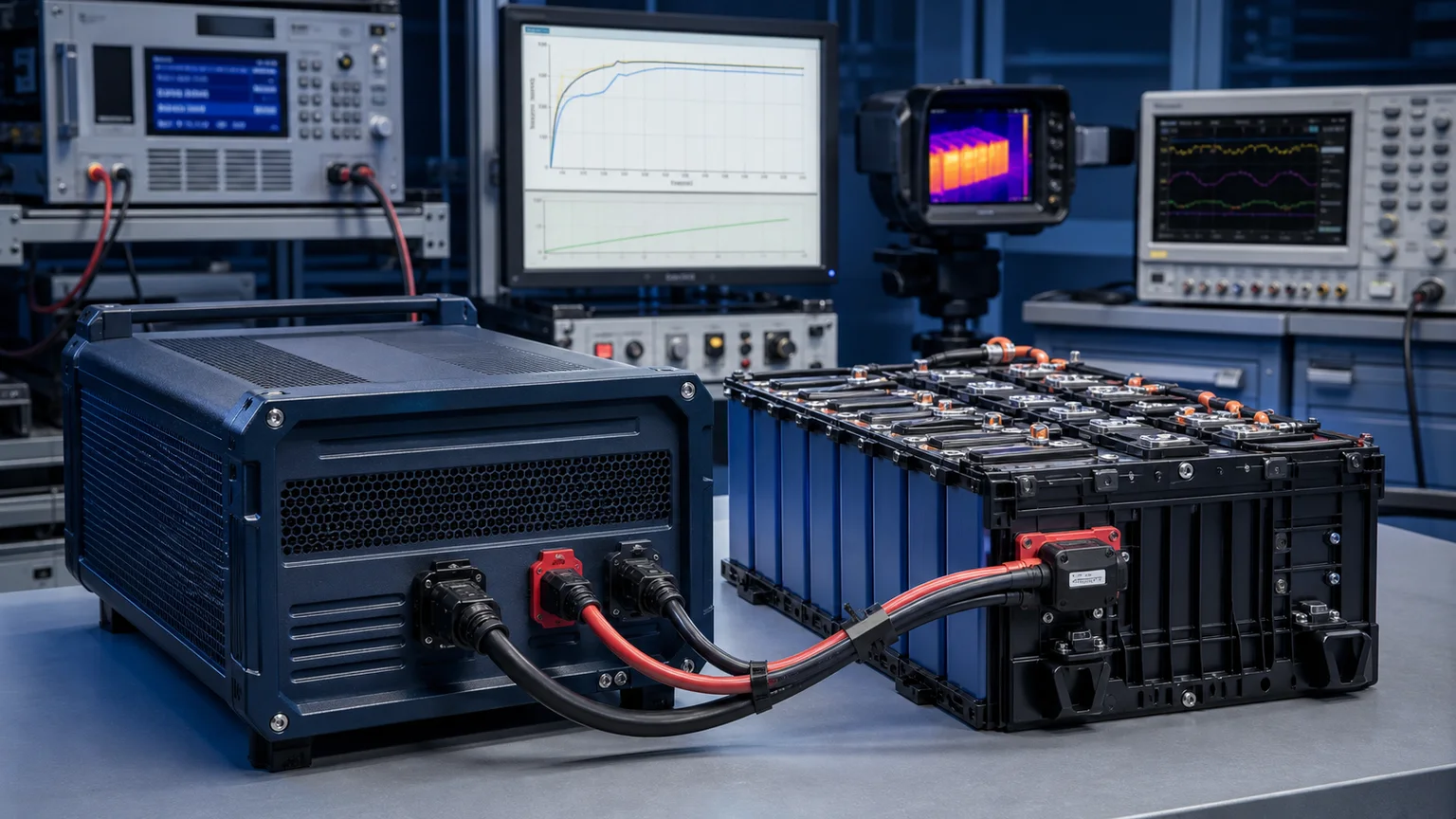

A marine battery charger is not a benchtop charger that happens to live near water. A boat charger sits inside a sealed engine room or under a console with a salt-laden bilge two feet below, runs through a 200-mile passage at 35°C ambient, takes a green-water boarding through a deck hatch every couple of years, and has to keep three or four separate battery banks at three different voltages and chemistries alive — all while the boat owner is asleep or two months away from the dock. Pick the wrong charger and you don't lose a hobby battery: you lose your starting bank in heavy weather, your house bank on the second night offshore, or your trolling-motor pack the morning of a tournament.
This guide covers marine battery charger selection in 2026 — how to size by voltage class, how to lay out a multi-bank on-board charger across starter / house / thruster / trolling banks, what ABYC A-31 and ABYC E-11 actually demand of the install, why an IP67 rating still isn't enough on its own for a true marine environment, and how to choose chargers that handle both legacy flooded / AGM banks and the wave of LiFePO4 retrofits sweeping recreational and commercial boats since 2024.
Why Marine Chargers Are a Category of Their Own
Land-based industrial chargers fail in marine service for three reasons that have nothing to do with current rating. Salt aerosol — a continuous fog of chloride that penetrates any enclosure with a breathing port — corrodes connectors, output terminals, and any unprotected copper. Vibration from a planing hull at 35 knots is closer to a forklift on a concrete dock than to a server in a rack. And the load profile is asymmetric: the starter bank wants a high-current top-up after every engine start while the house bank wants a long, slow absorption cycle and the trolling-motor pack wants a deep daily discharge.
This is why a marine-grade charger is built differently from its industrial cousin. The enclosure is potted or conformally sealed against salt fog (compliant with IEC 60068-2-52 salt-mist testing). The output terminals are stainless or tin-plated copper, never bare brass. The cabinet is rated for an angle of inclination — a boat heels 30° on a tack, and a charger whose internal cooling depends on a vertical fan path will overheat. And the protection envelope is wider: input transients from a poorly grounded shore-power pedestal at a fuel dock routinely hit 4–6 kV, far beyond what a typical 230/115 V industrial supply ever sees.
For a deeper view of the enclosure side of the question — IP65 vs IP67 vs IP68 and where the marketing claims fall apart — our waterproof power supply selection guide walks through exactly which rating belongs on which mounting location aboard a boat.
Step 1: Match the Charger to Your Voltage Class
Marine systems run on four nominal bus voltages. The voltage class is dictated by the boat's existing system architecture and the trolling-motor or thruster spec — you do not get to pick it freely once the boat is built.
| Boat type | Typical bank | Typical capacity | Typical charger output range |
|---|---|---|---|
| Center-console / runabout (single engine, single bank) | 12V | 80–150 Ah | 14.2–14.6 V (lead acid) / 14.2–14.6 V (LFP) |
| Cruiser, sailing yacht (starter + house) | 12V starter, 12V or 24V house | 150–600 Ah house | 14.4 V / 28.8 V absorption |
| Bass / tournament boat with trolling motor | 12V starter + 24V/36V trolling | 100 Ah starter, 200–400 Ah trolling | 14.4 V / 28.8 V / 43.2 V |
| Offshore sportfish, mid-size powercat | 12V or 24V house, 36V thruster | 400–800 Ah house | 14.4 V / 28.8 V / 43.2 V |
| Electric tender, hybrid yacht auxiliary | 48V propulsion bank | 200–500 Ah | 56.8–58.4 V (LFP) / 57.6–58.8 V (lead acid) |
Trolling-motor rigs are the source of most marine charger sizing confusion. A 36V trolling motor pack is built from three 12V batteries in series — but the on-board charger must be a true 36V three-output unit, not three independent 12V chargers wired blindly to the series string. Three independent 12V chargers will fight the series-stack voltage division, overcharge one battery and undercharge another, and shorten pack life in about a season. The same logic applies to a 24V trolling pack: use a true two-bank 24V or two synchronised 12V outputs.
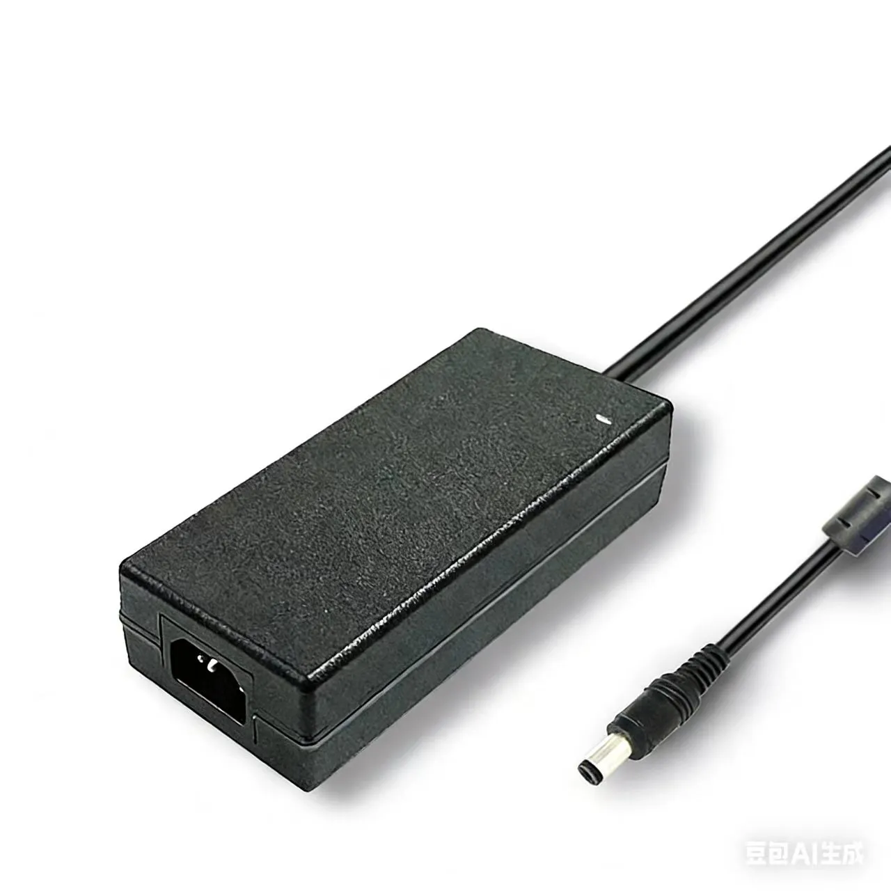
For the 48V LFP propulsion banks now appearing on electric tenders, hybrid yacht thruster systems, and the new generation of solar-cat designs, a charger like the SY-C1000W series ultra high-power charger (1000W / 1200W / 1600W, up to 25 A) sized to deliver a 0.2–0.3 C bulk current is the right scale of hardware — light-duty 10 A automotive chargers undersize badly at this pack capacity.
Step 2: Decide the Bank Count — Why "Multi-Bank" Is Not Optional
A typical cruising sailboat or sportfish boat has at least three independent battery banks:
- Engine starter bank — high cranking amps, shallow discharge, lead acid or AGM (lithium starting batteries are still uncommon outside racing builds).
- House bank — deep cycle, often two or three times the capacity of the starter, increasingly LiFePO4 on builds since 2023.
- Bow thruster / windlass bank — high burst current, light cycling, mounted forward and far from the engine room.
- (Optional) Trolling motor or electric propulsion bank — 24V, 36V, or 48V, deep cycle.
ABYC E-11 explicitly requires bank isolation: the starter must never be drained by the house, and a fault in any bank must not propagate. A multi-bank charger handles that isolation on the DC output side — each output is galvanically separated from the others, so a short on the house bank does not pull the starter bank down.
The wrong way to do this is to install one big charger and run a manual battery selector switch. That works on a calm day at the dock. It fails on a wet night at sea when the watch-keeper forgets to flip the switch and finds the starter bank at 11.3 V at 0300. A true 2- or 3-output charger eliminates that human-error path entirely.
The right way is to match output count to bank count. A 2-output charger covers starter + house. A 3-output covers starter + house + thruster. A trolling-motor rig usually needs a dedicated on-board 3-bank 12V or a single true 36V multi-bank output running off shore power overnight.
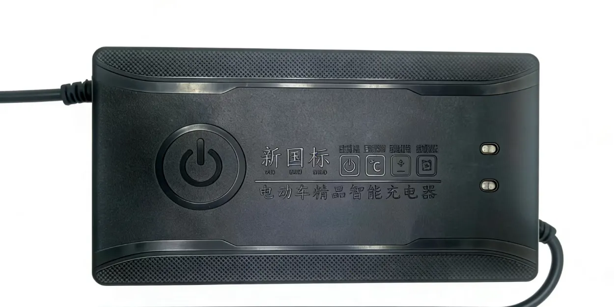
For mid-size boats running a 12V starter and a 12V or 24V LFP house bank, the SY-C500W-10A high-power charger sized as the house-bank charger paired with a smaller dedicated starter-bank unit is a clean two-charger architecture that sidesteps the "one charger does everything badly" trap.
Step 3: Pick the Right Charge Profile for the Chemistry on Board
Marine fleets are messy. A 2018 cruising sailboat may still have flooded house batteries, a 2022 sportfish has AGM, a 2025 power-cat is running LiFePO4 across every bank. A modern multi-bank marine charger must support all three profiles, and the profile selection must be per output, not a single global setting.
Flooded & AGM — 3-stage with EQ optional
Both flooded and AGM lead-acid banks accept a classic bulk → absorption → float profile. Flooded banks additionally benefit from periodic equalization (EQ) to remix stratified electrolyte. EQ is prohibited on AGM (boils sealed cells dry) and on gel (irreversible electrolyte damage). On a multi-bank charger, EQ must be selectable per output — running EQ on an AGM output because the user forgot to disable it will destroy a $400 battery in a single overnight cycle.
LiFePO4 — CC/CV with BMS handshake
LiFePO4 marine packs use CC/CV charging, no float, no EQ. The bulk stage pushes rated current until pack voltage reaches 3.55–3.65 V/cell (≈ 14.2–14.6 V on a 12V bank, 56.8–58.4 V on a 48V bank), then the CV stage tapers current to a cutoff threshold. After termination the charger sits idle until pack voltage falls below a re-bulk threshold.
The harder part is BMS coordination. A serious marine LFP bank carries its own BMS, and a charger that ignores BMS-asserted current-limit or temperature-cutoff signals will either trip the pack contactor mid-cycle — leaving the operator with an unexplained "charger keeps clicking on and off" — or push current at sub-zero pack temperatures and plate lithium onto the anode, permanently killing capacity within weeks. A charger built for LFP marine service must support a CAN or RS-485 BMS handshake, or at minimum a low-temperature charge inhibit.
For a full breakdown of the chemistry-specific tradeoffs and how to spot a charger that will quietly kill the wrong bank, the LiFePO4 vs lead acid battery charger selection guide is the reference companion to this article. For shoppers comparing aftermarket consumer brands head-to-head, the NOCO vs CTEK vs Victron LiFePO4 charger comparison covers the trade-offs at the small-bank end of the market.
Step 4: ABYC A-31, E-11, and What the Survey Will Look For
Two ABYC standards govern most of what a marine charger has to satisfy in North American waters. Compliance is voluntary on paper, mandatory in practice — insurance surveyors check for it, and a charger install that violates either standard is a flagged finding on a pre-purchase survey.
ABYC A-31 — Battery Chargers and Inverters. The primary marine charger standard. Covers ignition protection (charger must not be a source of ignition for engine-room fuel vapours), output isolation between banks, AC/DC galvanic isolation, leakage current limits to prevent stray-current corrosion of underwater metals, and protective behavior on input over/undervoltage.
ABYC E-11 — AC and DC Electrical Systems on Boats. The wider electrical-system standard. Specifies branch-circuit overcurrent protection within 7 inches of the battery, conductor sizing for marine ampacity tables (more conservative than residential), tinned-copper wiring throughout, and bonding requirements that affect how the charger ground is run back to the boat's bonding system.
Beyond ABYC, a charger destined for European or Asian markets should additionally carry:
- IEC 60945 — Maritime navigation and radiocommunication equipment. General environmental and EMC requirements for marine electronics.
- EN 60335-2-29 — Battery charger safety. Harmonised under the EU Low Voltage Directive. Required for CE marking on a marine charger sold into the EU.
- CE / FCC Part 15B — EMC emissions limits that prevent the charger from blanketing the boat's VHF or GPS receiver.
A multi-bank on-board charger sold without ABYC A-31 attestation is not, by industry definition, a marine charger — regardless of how the listing describes it. Ask for the test report, not the marketing copy.
Step 5: Saltwater Survival — IP67 Is the Floor, Not the Ceiling
Marine charger marketing leans heavily on the IP rating. Here is what the rating actually buys and where it stops mattering.
IP66 — Dust-tight, protected against powerful water jets. Acceptable for a charger mounted in a dry engine compartment that sees splash but not immersion.
IP67 — Dust-tight, protected against temporary immersion (1 m for 30 minutes). The baseline for any charger mounted below deck or in a wet locker. Most reputable on-board marine chargers carry IP67.
IP68 — Dust-tight, protected against continuous immersion under conditions specified by the manufacturer. Required only for bilge-area mounting where standing water is expected.
What IP ratings do not test for is what kills marine chargers in service: salt-mist corrosion, humidity cycling between 30% and 95% RH twice a day, and vibration from a planing hull. The relevant standards are IEC 60068-2-52 for salt-mist (look for at least 96 hours of cyclic exposure with no functional degradation), IEC 60068-2-30 for damp-heat cycling, and IEC 60068-2-6 for sinusoidal vibration up to 5 g across 10–500 Hz.
A charger with IP67 plus a published 96-hour salt-mist report is genuinely marine-grade. A charger with IP67 alone and no salt-mist report is an industrial charger in a sealed box — it will pass a brief immersion test on day one and corrode internally within two seasons of coastal cruising.
For a buyer who wants to put numbers on the inland vs coastal vs offshore trade-offs and understand what each IP digit really protects against, the IP65 vs IP67 vs IP68 waterproof power supply guide is the deep-dive companion to this section.
Step 6: Shore Power, Generator, and Solar Inputs — The Charger Must Survive All Three
A marine charger lives between three messy input sources and the battery banks. Each input source has its own failure mode.
Shore power (115 V or 230 V, 50/60 Hz, transient-loaded). Marina pedestals are notorious for poor grounding, neutral-bond faults, and overvoltage events when a shore-side generator transfer kicks in. A marine charger must accept a wide input range (typically 90–264 V AC), tolerate up to 4 kV input surge per IEC 61000-4-5, and continue operating through brief shore-power dropouts that would crash a desktop UPS.
Genset (engine-driven generator, 115 V or 230 V, marginal regulation). A small boat genset under load runs ±15% off nominal voltage and 5–7% off frequency. A charger that limits input current cleanly at the genset's continuous rating prevents the most common nuisance trip on a boat with a 3.5 kW genset trying to run a 1.5 kW charger plus a galley load.
Solar / DC-DC top-up (12 V / 24 V / 48 V). Increasingly common on cruising sailboats. The charger needs to coexist with an MPPT solar controller on the same bank — the two charging sources must agree on absorption setpoints, or one will keep cycling the other.
A multi-bank marine charger like the SY-C1000W series, sized at 1000–1600 W with up to 25 A output, can handle 48 V LFP propulsion banks plus a 12 V starter top-up on a single AC input, with input-current limiting that respects a 3.5 kW genset. The smaller SY-C260W-5A high-power charger covers the dedicated 24 V auxiliary or trolling-motor maintenance use case where a smaller, lighter unit makes sense.
You can browse the full Sanyi marine and industrial charger range from the products listing, or request a sizing recommendation from our engineering team.
FAQ
How do I size a marine charger to my battery bank capacity?
The conventional rule for a deep-cycle marine bank is 10% to 25% of bank capacity in amps — a 300 Ah house bank therefore wants a 30–75 A charger. Below 10%, the charge time is unacceptable for a weekend cruiser. Above 25%, the charger over-stresses lead-acid plates and starts running into BMS limits on LFP banks. For LiFePO4 banks specifically you can safely go to 0.5 C on charger output if the BMS supports it, but the genset and shore-power input is usually the limiting factor long before the battery is.
Can one on-board charger handle a 12V starter, a 24V house bank, and a 36V trolling motor?
Yes if it is a true three-output marine charger with independently configurable per-output voltage and chemistry profiles. No if it is a single-output charger fed through a battery isolator or a manual switch. The independently configurable output is non-negotiable because the three banks will be at three different states of charge after a typical day of running, and a one-size-fits-all output will undercharge two of the three.
Is IP67 enough for a charger mounted in the engine room?
IP67 is the right enclosure rating for engine-room mounting (it covers the brief-immersion case from a deck-hatch boarding) but it is not sufficient on its own for marine service. Ask for an additional IEC 60068-2-52 salt-mist test report (96 hours minimum) and an IEC 60068-2-6 vibration spec. A charger that publishes IP67 with no salt-mist or vibration data is an industrial charger relabelled for the marine market.
What's the difference between an "on-board" marine charger and a portable boat charger?
An on-board charger is permanently wired, dedicated to the boat, ABYC A-31 compliant, isolated from the AC mains, and designed to be left on while the boat is unattended at a dock for weeks. A portable boat charger is essentially a beefier automotive charger — fine for top-up at home in the garage, not safe to leave on a boat plugged into shore power unattended. ABYC surveyors will flag the latter as a safety finding.
Can I keep my old flooded lead-acid bank if I retrofit a LiFePO4 house bank on the same boat?
Yes, but the charger has to handle both. A multi-bank marine charger with per-output profile selection is the only clean way to do this — set one output to flooded 3-stage with periodic EQ, set the other to LFP CC/CV with low-temperature cutoff and BMS handshake. Trying to run both banks off one global profile will either sulfate the lead-acid bank (LFP profile undercharges it) or trip the LFP BMS (lead-acid EQ overvoltages the LFP cells).
Do I need a different charger for saltwater vs freshwater boating?
A freshwater-only boat (Great Lakes, large rivers, inland lakes) can often get by with an industrial charger in a sealed enclosure, because the salt-mist failure mode is absent. A saltwater boat — coastal cruiser, sportfish, offshore sailor — needs the full marine-grade build: salt-mist tested, tin-plated terminals, conformally coated boards, ignition-protected enclosure. The price delta is usually 30–50%, and the lifetime delta is 3× to 5× in coastal service.
What certifications should I require on a marine charger sold into the US?
ABYC A-31 for the charger itself is the primary one — without it, the charger is not a marine charger by industry definition. ABYC E-11 governs the install. UL 1236 is the older but still cited UL standard for battery chargers in marine applications. FCC Part 15B covers EMC emissions. For boats also exporting to or operated in Europe and Asia, CE marking with EN 60335-2-29 + EN 55014 and IEC 60945 (for offshore vessels carrying SOLAS-grade nav equipment) are the additional layers.
Conclusion
Marine charger selection is a four-decision problem made in order: voltage class (set by the boat's existing bank architecture and any trolling/propulsion pack), bank count and output isolation (set by ABYC E-11 and how many independent banks the boat carries), per-output chemistry profile (set by which banks are flooded / AGM / LFP), and enclosure / certification (set by ABYC A-31, IP rating, and the salt-mist / vibration environment). Get the order right and the hardware decision is straightforward — Sanyi's high-power charger line, from the SY-C260W single-bank auxiliary chargers up through the SY-C500W mid-bank units and the SY-C1000W ultra-high-power 48 V class, spans the full envelope from trolling-motor maintenance to offshore LFP propulsion banks.
If you are repowering a cruising boat with a LiFePO4 house bank, building a tournament rig with a 36 V trolling motor and a 12 V starter, or specifying chargers for a new electric tender or hybrid yacht, talk to our engineering team with the boat type, bank count, capacity per bank, chemistry per bank, AC-input source (shore power / genset / both), and the typical operating environment — and we will come back with a multi-bank charger spec and an install layout tuned to the actual duty cycle.
.webp)