


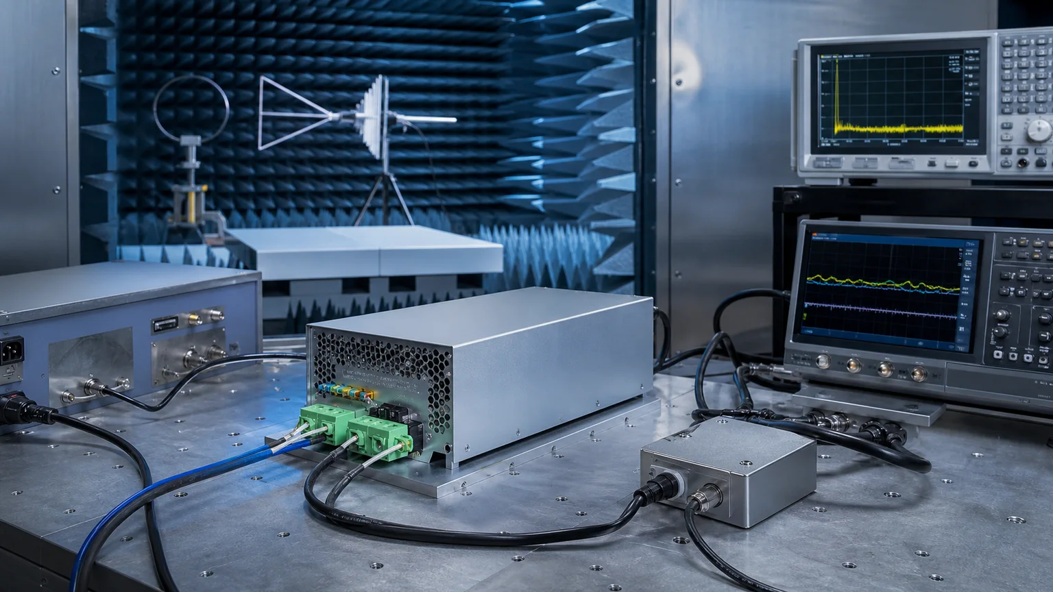

A power adapter can pass every emission test — clear CISPR 32 Class B, hold a flawless conducted/radiated margin — and still come back from the field dead. The failure mode that surprises engineers most is the mirror image of emissions: not the noise the adapter sends out, but the abuse it has to survive. A nearby lightning strike couples a surge onto the mains; a user shuffles across carpet and zaps the connector; a relay coil kicks a fast transient onto the power line; the grid sags during a motor start. Any one of these can latch up, reset or permanently kill a converter that sailed through emissions. That second half of EMC is immunity, and it is governed by the IEC/EN 61000-4 family of basic test standards.
This guide compares the core immunity tests side by side — IEC 61000-4-2 ESD, IEC 61000-4-4 EFT/burst, IEC 61000-4-5 surge, IEC 61000-4-11 voltage dips plus conducted and radiated immunity — what each one injects, where the residential and industrial levels fall, how performance criteria A/B/C/D are scored, and which protection components keep an external power supply alive.
Why an Adapter That Passed EMI Still Dies in the Field
Emissions and immunity are the two halves of EMC, and they are tested by completely different equipment. Passing CISPR 32 / EN 55032 proves your adapter is a quiet neighbour — it does not prove it is a tough survivor. The EU EMC Directive (2014/30/EU) makes both halves a hard prerequisite for the CE mark: emissions under EN 55032, and immunity under the generic standards EN 61000-6-1 (residential) or EN 61000-6-2 (industrial), which in turn call up the IEC 61000-4-x basic tests. A unit can have best-in-class efficiency, an IEC 62368-1 safety listing and Class B emissions and still be non-compliant — and unsellable — if a ±2 kV surge resets it or an ±8 kV ESD discharge corrupts its MCU. Worse, immunity faults surface late and intermittently: they are the "it works on the bench but dies at the customer site" bugs. This guide is the immunity twin of our CISPR 32 vs FCC Part 15 Class B EMI emissions guide — together the two cover the full EMC picture.
The Five Pillars of EMC Immunity
For an external power supply, immunity testing rests on a handful of basic standards, each simulating a real-world disturbance:
- IEC 61000-4-2 — Electrostatic Discharge (ESD): a charged human or object touching the enclosure or connector.
- IEC 61000-4-4 — Electrical Fast Transient / Burst (EFT): bursts of fast spikes from relay/contactor switching coupled onto power and signal lines.
- IEC 61000-4-5 — Surge: the high-energy combination wave from lightning and grid switching events.
- IEC 61000-4-11 — Voltage Dips, Short Interruptions and Variations: the mains sagging, dropping out or flickering.
- IEC 61000-4-6 / -4-3 — Conducted and Radiated RF Immunity: continuous RF energy injected onto cables or radiated as a field.
Each test has its own generator, coupling network, level table and pass/fail (performance) criterion. Get any one wrong and the whole CE/EMC file stalls.
IEC 61000-4-2: Electrostatic Discharge (ESD)
ESD simulates the static a person accumulates and then dumps into the product. The ESD gun charges a 150 pF capacitor and discharges it through a 330 Ω resistor — the "human-body" model that defines the current waveform's sub-nanosecond rise and tens-of-nanoseconds decay. Two application methods are used:
- Contact discharge — the electrode touches a conductive surface (metal shell, connector shield, screw). Test levels are typically ±4 kV (level 2) and ±8 kV (level 4).
- Air discharge — the charged electrode approaches an insulating surface until it arcs over. Levels are typically ±8 kV and ±15 kV (level 4).
Discharges are applied to every point a user can touch — the enclosure seams, the DC output connector, USB ports — and to horizontal/vertical coupling planes near the unit. ESD energy is low but its dV/dt is brutal: the failure is usually a logic upset (reset, output glitch, lost USB-PD handshake), not a burned part. The cure is a low-impedance discharge path to chassis/ground and TVS clamps on exposed I/O.
IEC 61000-4-4: Electrical Fast Transient / Burst (EFT)
EFT reproduces the bursts thrown onto wiring when an inductive load — a relay, contactor or motor — switches. The waveform is a 5/50 ns spike (5 ns rise, 50 ns to half-value) delivered in bursts: packets of spikes at 5 kHz or 100 kHz repetition, 15 ms bursts every 300 ms. Test levels for an adapter:
- AC/DC power ports: typically ±1 kV (level 2, residential) up to ±2 kV (level 3/4, industrial).
- Signal/control ports: typically ±0.5 kV to ±1 kV.
Power-port EFT is applied through a CDN (coupling/decoupling network); signal and longer cables use a capacitive coupling clamp that injects the burst without a galvanic connection. Like ESD, EFT energy per spike is small, but the high repetition rate hammers the input continuously — the classic failure is spurious resets or false triggering of the controller. An input common-mode choke plus an X-cap and an MOV/TVS at the input usually tames it.
IEC 61000-4-5: Surge (Lightning and Grid Switching)
Surge is the high-energy heavyweight. It simulates an indirect lightning strike or a major grid switching event using the combination wave generator: an open-circuit 1.2/50 µs voltage waveform paired with a 8/20 µs current waveform (2 Ω effective source impedance for line-to-line, higher for line-to-ground). Because the energy is orders of magnitude above EFT, surge is what actually destroys hardware. Coupling and test levels:
- Line-to-line (L-N): typically ±0.5 kV / ±1 kV / ±2 kV.
- Line-to-earth (L-PE, N-PE): typically ±2 kV / ±4 kV (the ground-referenced paths take the higher stress).
Surge is applied at multiple phase angles (0°, 90°, 270°) because the worst case depends on where on the AC sine the strike lands. The defence is an energy-absorbing front end: an MOV to clamp the bulk energy, often backed by a GDT on the line-to-earth path and a fuse upstream to fail safely. An adapter with no MOV will reliably die at ±2 kV — this is the single most common immunity teardown finding.
IEC 61000-4-11: Voltage Dips, Short Interruptions and Variations
Real mains is not a clean 230 V/50 Hz (or 120 V/60 Hz) source. Motors starting, faults clearing and load steps make the voltage dip, drop out or vary. IEC 61000-4-11 tests how an adapter rides through:
- Dips: voltage reduced to a percentage of nominal for a number of cycles — common combinations are 70% for 25 cycles, 40% for 10/12 cycles, and 0% for 0.5/1 cycle.
- Short interruptions: voltage to 0% for 250 cycles (≈5 s at 50 Hz) — a true dropout.
- Voltage variations: a gradual ramp down and back up.
The key design parameter is hold-up time — how long the bulk capacitor keeps the output in regulation after input is removed. The performance criterion depends on depth and duration: a shallow dip should not disturb the output at all (Criterion A), while a full interruption may legitimately let the output collapse, provided the unit restarts cleanly and on its own when power returns (Criterion B or C). The failure that fails the test is a converter that latches off and will not restart, or restarts into a fault.
IEC 61000-4-6 and -4-3: Conducted and Radiated RF Immunity
The last pillar is continuous RF energy — the immunity counterpart of radiated/conducted emissions:
- IEC 61000-4-6 (conducted immunity): RF from 150 kHz–80 MHz is injected onto power and signal cables through a CDN at field strengths equivalent to 3 V (residential) or 10 V (industrial), 80% AM modulated.
- IEC 61000-4-3 (radiated immunity): the unit sits in an anechoic chamber bathed in a field of 3 V/m (residential) or 10 V/m (industrial) over 80 MHz–1 GHz, often extended to 1–6 GHz for modern wireless bands.
These tests probe whether ambient RF (a nearby transmitter, a phone, a Wi-Fi router) sneaks into the feedback loop and shifts the output or trips protection. Good PCB grounding, shielding and filtering — the same discipline that keeps emissions down — generally buys immunity here too.
Generic Immunity Levels: EN 61000-6-1 vs EN 61000-6-2
An adapter rarely cites the basic 61000-4-x standards directly; it declares conformity to a generic immunity standard that bundles them at the right severity for the environment. The two that matter for power supplies are EN 61000-6-1 (residential, commercial, light-industrial) and EN 61000-6-2 (industrial). The industrial standard demands materially higher surge, EFT and RF levels:
| Immunity test | EN 61000-6-1 (residential) | EN 61000-6-2 (industrial) |
|---|---|---|
| ESD (61000-4-2) | ±4 kV contact / ±8 kV air | ±4 kV contact / ±8 kV air (often ±6/±15) |
| EFT power port (61000-4-4) | ±1 kV | ±2 kV |
| Surge L-N (61000-4-5) | ±1 kV | ±2 kV |
| Surge L-PE (61000-4-5) | ±2 kV | ±2 kV (often ±4 kV) |
| Conducted RF (61000-4-6) | 3 V | 10 V |
| Radiated RF (61000-4-3) | 3 V/m | 10 V/m |
| Voltage dips (61000-4-11) | Yes | Yes (stricter ride-through) |
A consumer USB-PD or desktop adapter targets EN 61000-6-1; a supply destined for factory floors, building automation or telecom needs the EN 61000-6-2 levels — roughly a doubling of surge/EFT energy and triple the RF field. Designing to residential and then dropping the unit into an industrial socket is a guaranteed field-return generator.
Performance Criteria A / B / C / D
Immunity is not simply pass/fail — the standard defines how degraded the product may be during and after each disturbance. The acceptable criterion is set per test by the generic standard:
| Criterion | Behaviour during/after the disturbance | Typical use |
|---|---|---|
| A | Normal performance, no deviation outside spec — output never moves | Continuous phenomena: conducted/radiated RF, shallow dips |
| B | Temporary degradation or loss of function that self-recovers with no operator action | Transient phenomena: EFT, surge, deeper dips |
| C | Temporary loss of function requiring operator intervention (e.g. a power cycle) | Severe interruptions |
| D | Loss of function not recoverable — damage, lost data | Not acceptable — equals a fail |
For an external adapter the realistic targets are Criterion A for RF and shallow dips (the output must stay rock-solid) and Criterion B for surge, EFT and full interruptions (a momentary glitch or a clean auto-restart is allowed, but the unit must never need a human to unplug it, and must never be damaged). Criterion D is always a fail.
Immunity Protection Component Design
Surviving the four transient tests comes down to a layered front-end that grades the energy down from kilovolts to something the silicon can swallow:
- MOV (metal-oxide varistor): the workhorse for surge. Connected L-N (and often L-PE/N-PE), it clamps the bulk 8/20 µs energy. Sized by clamping voltage and joule rating; pair with an upstream fuse so a failed MOV opens safely.
- GDT (gas discharge tube): very high energy capacity and near-zero leakage; used on line-to-earth paths and in series with an MOV to handle the highest surge levels without the MOV's standing leakage.
- TVS diode: fast, low-clamp protection for low-voltage I/O — the DC output, USB-PD data/CC lines, signal ports. It catches ESD and residual EFT that gets past the front end before it reaches the MCU.
- Common-mode choke (CMC): high impedance to the common-mode component of EFT and surge transients; the same choke that helps emissions also blunts incoming bursts.
- Y-capacitor: shunts common-mode transient energy to ground — but its value is bounded by the safety earth-leakage budget (commonly ≤0.25 mA for a Class II adapter), so it cannot be enlarged freely.
The art is coordination: the MOV/GDT clamps the kilovolt surge, the CMC and X/Y-caps filter the EFT burst, and the TVS mops up the fast ESD residue at each exposed connector. Get the staging wrong — a TVS asked to absorb surge energy, or an MOV expected to clamp ESD fast enough — and a part that looks present on the schematic still lets the unit fail.
Five Common Immunity Debug Pitfalls
- No MOV on the input — instant surge death. The most frequent teardown finding: a cost-reduced front end with no varistor dies the moment ±2 kV hits L-N. Surge energy has to be absorbed, not filtered; an EMI filter alone will not save it.
- Ungrounded or high-impedance enclosure — ESD upsets. If the metal shell or connector shield has no low-impedance path to chassis/PE, an ±8 kV contact discharge routes through the PCB and resets the controller. Give ESD a deliberate path around the electronics.
- EFT triggers spurious restarts. Burst transients couple into the control IC's enable or feedback pin and false-trigger a shutdown. A common-mode choke plus local TVS/RC filtering on the sensitive pins fixes what looks like a "random reset" in the field.
- Voltage-dip lock-up — the unit won't restart. A converter that latches into a fault on a 0%/250-cycle interruption and needs a manual unplug fails Criterion B. The supervisor must auto-retry cleanly when the mains returns.
- Signal-port TVS clamps above the MCU's limit. A TVS chosen for a high working voltage clamps at, say, 12 V while the MCU's I/O absolute-max is 3.6 V — so ESD/EFT still kills the pin. Match the clamp voltage to the protected rail, not the bus voltage.
Sanyi Power Supply Ecosystem — IEC 61000-4 Immunity Verified
Sanyi engineers its USB-PD, GaN and desktop adapter lines to pass the full IEC 61000-4-2 / -4-4 / -4-5 / -4-11 immunity suite to EN 61000-6-1 residential levels — with an upgrade path to EN 61000-6-2 industrial severity for harsher deployments. The protection staging (MOV + GDT on the surge path, common-mode choke and X/Y filtering for EFT, TVS clamps on every exposed I/O) is built into the platform rather than bolted on. For high-power applications, the HP high-power adapter series (up to 240W) carries the surge and EFT margin needed at high throughput. The APN desktop adapter series brings the same immunity discipline to mid-power desktop and IT loads. For multi-port and workstation charging, the SY-C260W multi-mode charger and the higher-output SY-C500W high-power charger hold their ESD and surge ride-through even in GaN-dense designs.
Because immunity, emissions, safety and efficiency are one compliance package, our adapters are designed to satisfy all four together — pairing this immunity work with the emissions side in the CISPR 32 vs FCC Part 15 Class B EMI guide, the safety chain in the IEC 62368-1 safety standard migration guide, and the internally generated surge story — startup inrush rather than grid lightning — in our inrush current limiting guide. Contact our power engineering team with your power, port and destination-market requirements and we will recommend a compliant platform and the matching immunity test data.
FAQ
Is immunity the same as emissions testing? No — they are the two opposite halves of EMC. Emissions (CISPR 32 / EN 55032) measure the noise your adapter sends out onto the mains and into the air. Immunity (the IEC 61000-4-x family) measures whether your adapter survives disturbances coming in — surge, ESD, EFT, dips, RF. A product needs both to earn a CE mark under the EMC Directive, and passing one tells you nothing about the other.
How do I choose between EN 61000-6-1 residential and EN 61000-6-2 industrial levels? Match the standard to where the adapter will actually be plugged in. EN 61000-6-1 (residential/commercial/light-industrial) is right for consumer chargers, desktop adapters and office equipment. EN 61000-6-2 (industrial) roughly doubles the surge/EFT energy and triples the RF field, and is required for factory-floor, building-automation and telecom deployments. Designing to residential and shipping into an industrial environment is a classic source of field returns.
Why are USB-PD adapters especially vulnerable to surge? Two reasons. First, aggressive cost and size optimisation sometimes thins out the surge front end — an undersized or missing MOV cannot absorb the 8/20 µs energy. Second, the USB-PD data/CC lines and the low-voltage DC output are directly exposed at the connector, so ESD and residual EFT reach sensitive silicon easily. A robust design needs a properly rated MOV (with fuse backup) on the input and TVS clamps matched to each I/O rail.
What is the difference between ESD contact and air discharge? Both come from the same ESD gun (150 pF / 330 Ω human-body model). Contact discharge touches the electrode directly to a conductive surface and is the repeatable, primary method — typically ±4 kV/±8 kV. Air discharge is used on insulating surfaces: the charged electrode approaches until it arcs across the gap — typically ±8 kV/±15 kV. Air discharge is less repeatable (it depends on humidity and approach speed) but reaches points contact cannot.
How do MOV, GDT and TVS divide the work in a protection front end? They stage the energy down by speed and capacity. The MOV absorbs the bulk surge energy (kilovolts, 8/20 µs) at the input. A GDT backs it up on line-to-earth paths, handling the very highest energy with near-zero standing leakage. The TVS diode is fast and low-clamping, sitting at each exposed low-voltage I/O to catch ESD and the EFT residue that slips past the front end before it reaches the MCU. No single component does all three jobs — coordination is what makes the design survive.
.webp)
.webp)